Single Phase Voltage Regulator RAV-2
with control CTR-2
Instruction Manual MI-010
Page: 1/27
Rev. 06/2017
TABLE OF CONTENTS
TABLE OF CONTENTS.........................................................................1
INTRODUCTION....................................................................................1
DESCRIPTION.......................................................................................1
Identification of high voltage terminals............................................3
Single phase between phase and earthed neutral .........................4
Two phase ......................................................................................4
Open Delta ......................................................................................4
Closed Delta....................................................................................4
Star ("Y")..........................................................................................5
EARTH CONNECTION OF A BANK OF REGULTORS ................5
CASCADED VOLTAGE REGULATORS...............................................5
Fault Effect......................................................................................5
Effect of operations avalanche........................................................5
RECEPTION..........................................................................................6
STORAGE..............................................................................................6
RISING...................................................................................................6
INSTALLATION......................................................................................6
Inspection before installation:..........................................................6
HEIGHT...........................................................................................7
Reference voltage...........................................................................7
SUPORT AND FIXING....................................................................8
High tension connections................................................................8
REGULATOR PLACEMENT IN SERVICE............................................8
Connections.....................................................................................8
Placing in service.............................................................................8
VERIFYING REGULATORS OPERATIONS.........................................9
REMOVING REGULATOR FROM SERVICE.......................................9
MAINTENANCE.....................................................................................9
General Instructions........................................................................9
REGULATOR OPENING.....................................................................11
TAP CHANGER....................................................................................11
WINDINGS...........................................................................................12
CONTROL CTR-2 ...............................................................................12
Components of Front Panel .........................................................14
Set of screens................................................................................14
Standard screen............................................................................15
Screen Shortcut.............................................................................15
Direct Command Key....................................................................15
Auto Zero.......................................................................................16
Navigation in reading screens.......................................................16
SETTINGS IN CONTROL – GENERAL VIEW...................................17
Navigation through the adjustment screens..................................17
CONTROL SETTINGS - DETAILS......................................................19
1 – VT relation for control unit.......................................................19
2 - CT relation for control unit .......................................................19
03 a 36 – Regulation parameters..................................................19
13, 16, 25 e 29 – validity week of map 2 and 3............................19
14, 17, 26 e 30 – Time to set active maps 2 and 3.......................20
15, 18, 27 e 31 – minute to set active maps 2 and 3....................20
24 – Month to set active map 3.....................................................20
28 – Amount of months where Map 3 is active.............................20
37 - Activation of automatic load bonus .......................................20
38 e 39 – Position lock and manual load bonus ..........................20
40 and 41 - Voltage lock ...............................................................20
42 – Overcurrent lock ...................................................................21
43 - Actuation mode in case of inverse flow ................................21
44 - Tap changer actuation, insensibility treatment and extreme
locks. .............................................................................................23
45 - Tap changer position Reading method .................................23
46 - Phase shift between voltage and current ..............................23
47 - Optional source voltage measurement .................................24
48 - Enabling Delayed return to automatic mode ........................24
49 – Locl limit ................................................................................24
50 - Datalogging period.................................................................24
51 - Inverse time enabling.............................................................24
52 – Regulator operation mode.....................................................25
53 - Serial communication address...............................................25
54 - Port 1 communication mode.................................................25
55 - Port 2 communication mode.................................................25
56 and 57 - Data transmission bound rate....................................25
58 – Enabling unsolicited message..............................................25
59 - Address for unsolicited message...........................................25
60, 61, 62, 63, 64 and 65 - Clock settings....................................25
OPERATING WITH EXTERNAL VOLTAGE SOURCE.......................26
LINE DROP COMPENSATION...........................................................26
INDICATOR IRT-1 (OPTIONAL)..........................................................27
ALTERNATIVE DRIVE.........................................................................27
INSOLATING OIL –FISPQ..................................................................27
LIFE CYCLE........................................................................................27
INTRODUCTION
ITB model RAV-2 single phase voltage regulators, with CTR-2
controls, are 32 step type B autotransformers created to measure
and correct voltage drop on distribution lines caused by its
impedance. They were designed to ensure easy installation and
operation and minimum maintenance exceeding those requirements
established under ANSI IEEE C57.15 and ABNT NBR 11.809.
All ITB voltage regulators are manufactured, tested and delivered
with standard parameters programmed beforehand, establishing
this as a suggestion for future operation. To obtain an accurate
performance to meet specific needs, user has to make settings to
its programming.
IMPORTANT: By reading completely this manual
you will follow adequate installation
recommendations, ensure secure handling of the
product, efficient operation and secure and reliable
maintenance .
DESCRIPTION
The voltage regulator is a dielectric oil immersed autotransformer
with serial winding on source side (type B) equipped with load tap
changer which in conjunction with the reactor allows 32 step
(neutral, 16 step raise, 16 step lower) voltage regulation achieving a
+/- 10% variation with 0,625% steps of nominal voltage variation .
ITB - Equipamentos Elétricos Ltda.
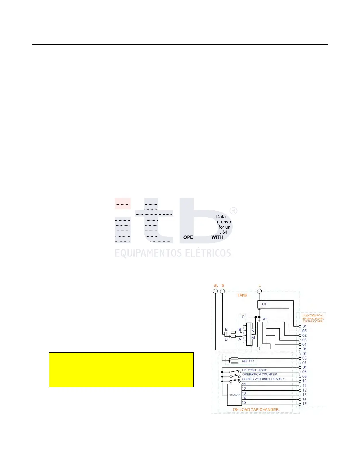
Figure 1: General diagram inside of the tank.