Single Phase Voltage Regulator RAV-2
with control CTR-2
Instruction Manual MI-010
Page: 6/27
Rev. 06/2017
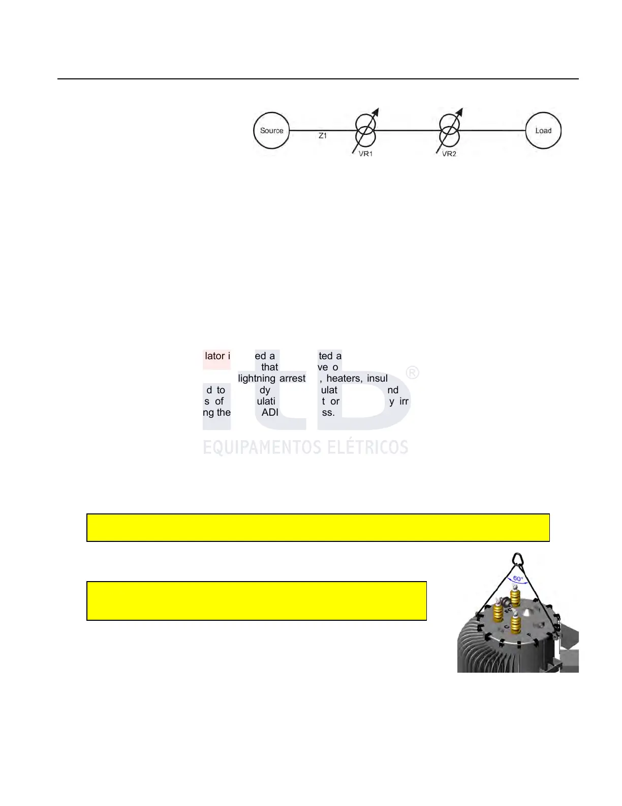
current. Current variation depending on network impedance Z1 from source to RT1, produces a voltage variation of
RT1.
Taps changes in one of RT2 regulators
to boost (raise), for example, can cause
a rise in current so significant on the
voltage regulator of RT1 bank in that
same phase, which can exceed the
insensibility programmed in that control
unit. If this occurs, the regulator control
unit of RT1 detects this imbalance and promotes its correction by changing its tap changer boosting its tap . This
change of RT1 , increases the phase voltage which is measured and perceived by the control unit of bank RT2,
which once again may be greater than the voltage insensitivity programmed in that control unit inducing a correction
which is done by the control unit changing the tap changer so as to buck (decrease) voltage , restarting the cycle of
interaction.
What happens then is a large amount of sequential operations between series installed regulators, which we call the
operations avalanche. This interaction shows the variations of increasing amplitude of voltage and current along the
network and can reach harmful levels of imbalance between phases with possible activation of the neutral current
protection .
For banks installed in delta , avalanches can occur between different phases and with greater intensity and
frequency due to increased regulation and the interaction between the phases.
Insensitivity coordination eliminates any possibility of operation avalanches.
RECEPTION
Before packing, the voltage regulator is tested and inspected at factory. Upon receipt, another inspection should be
performed to identify any possible damage that may have occurred during transport and handling. The optional
external position indicator, control box, lightning arresters, heaters, insulators, electrical cables and other external
components must be rigidly fixed to the body of the regulator, intact and free of cracks and deformations. The
packaging must not show signs of manipulation, impact or a fall. Any irregularities must be reported to ITB
immediately and before performing the UNLOADING process.
STORAGE
If the regulator is temporarily unloaded it must be stored in a ventilated, level ground site and away from heat
sources, sparks protected as to avoid mechanical damage.
RISING
When rising regulators with steel wire ropes or chains, it has to be done using the lifting lugs located on the side of
the tank
ATTENTION: Cover can be damaged if the internal assembling lifting eyes which are located on
the cover are used for regulator lifting and handling.
Steel wire ropes or chains used must be on good condition and be certified to withstand
voltage regulators weight with enough length to allow the angle between arms, with
vertex at the hook, be at least 60 degrees (see Figure 10).
DANGER: Usage of short steel wire ropes or chains causing angles
bigger than 60 degrees can cause strain on the regulator´s cover and
cause lifting lugs breakdown
In any rising operation regulator should remain leveled.
INSTALLATION
Inspection before installation:
Before connecting the regulator on service, perform the following inspection:
1. Check the oil level. If missing, check visible loss or filtering. In case no cause is
identified refill with naphthenic oil,
2. Examine there is no damage in surge arrestors nor its connection cables.
3. Inspect insulators (bushings) to check any possible damage or any indication of leakage at the joints. If there is a
filtration suspicion, remove the inspection cover to check for rust indication or water in the oil. If filtration is
confirmed contact ITB for appropriate method to solve this
ITB - Equipamentos Elétricos Ltda.
Figure 9: Cascade regulation.
Figure 10: Lifting method