Single Phase Voltage Regulator RAV-2
with control CTR-2
Instruction Manual MI-010
Page: 14/27
Rev. 06/2017
DNP 3.0 communication protocol in both comm ports;
3 independent setting maps for direct power flow activated
depending on date and time;
Real time clock and calendar;
On load tap changer protection in case of overload;
Switch protection in case of overload;
Accuracy of 0.7% of measured values in a 25°C environment.
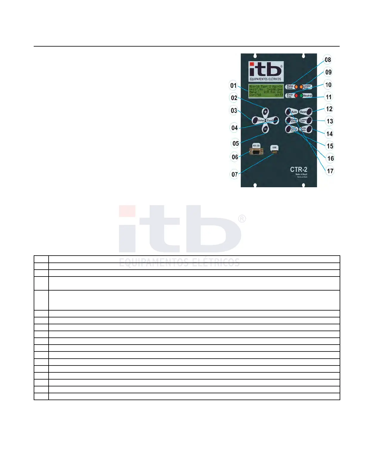
Components of Front Panel
With a simplified arrangement, CTR-2 control allows visualization
setting of control settings and instantaneous measurements readings of
the electrical system without the need for any other additional
accessory.
When CTR-2 control is energized all the LEDs and the back light of the
LCD screen lights up to test their correct operation and installation.
The front panel has a monochromatic alphanumeric LCD display and a
keypad, as shown in Figure 14 and described in Table 5.
All controls are individually tested and calibrated at factory and all
settings may be manually done through the keypad present on the front
of the CTR-2 unit. Through the navigation keys all information can be accessed and displayed and perform setting in
configuration .
Table 5: Front panel elements identification.
Item Description
01 LCD monochromatic display 4 lines 20 characters
02 “+” key allows navigation through screens as selected
03
“Selec” key allows user to select between measurements, adjustment or shortcut screens. When on
appropriate condition (configuration mode) it allows to move cursor to the left
04
“Conf” key on main screen changes voltage and current values between low tension and high tension
“Conf” key changes to configuration mode when on settings screens
“Conf” key confirms selected value of each adjusted digit
05 “-” key allows navigation through screens as selected
06 DB-9 serial comm port EIA-232
07 USB type A comm port
08 LED lit when need of correction to boost voltage
09 LED lit when need of correction to buck voltage
10 LED fault indication
11 LED lit when neutral position is confirmed
12 “Reset” key updates or resets values which allows that condition
13 “Lower” key changes on load tap changer in buck sense when “manual” mode in active
14 “Auto Zero” key takes on load tap changer into zero position (neutral).
15 “Local /Remote” key changes command operations only to local so as to avoid risks
16 “Raise” (Boost) key changes on load tap changer in boost sense when “manual” mode in active.
17 “Auto” key changes operation between automatic and manual mode
Set of screens
Screens of CTR-2 control were organized into 4 groups: standard screen displays measurements, numbered from
66 to 84, settings screen, numbered from 01 to 65, and shortcut screen. The "Select" key toggles between screens
of those 4 groups in the order in which they were described, always showing the first screen of each group. In each
group user can, from the main screen, press the "+" button to display the first measuring screen (screen 66), or
press the "-" key to display the last measurement screen, (84 screen), and from any screen user can browse the
group of screens by pressing "+" or "-".
ITB - Equipamentos Elétricos Ltda.
Figure 14: Font of the control.