Single Phase Voltage Regulator RAV-2
with control CTR-2
Instruction Manual MI-010
Page: 3/27
Rev. 06/2017
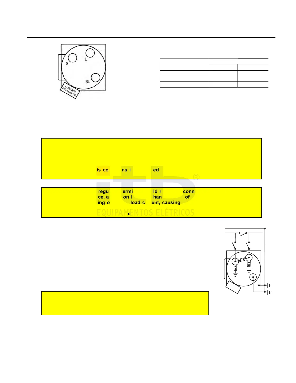
Identification of high voltage terminals
High Voltage isolators are identified as per ANSI or ABNT standard, as stated on Table 1 (by default as per ABNT
standard unless stated otherwise). This is an indelibly identification marked in cover by under relief and reinforced
with black paint.
DANGER: Due to possible neutral tension shift and rush in number of tap changings searching
for a reference it is not recommended to install voltage regulators in wye on a three phase
three wire distribution network unless neutral is connected to the neutral of a wye connected
transformer or to the substation transformer secondary neutral. For the connection or removal
on service of voltage regulators it is extremely important that the on load tap changer is in the
neutral position and this conditions is confirmed by, at least, two different means (position
indicator and neutral light).
DANGER: If SL voltage regulator terminal should remain unconnected, which means voltage
regulator has no reference, and its on load tap changer is out of neutral position high tensions
can be induced depending on actual load current, causing damage to equipment, injuries or
even death of personnel. Thus no equipment such as fuses, reclosers, circuit brakes or any
other are to be connected on the FC terminals derivations.
SYSTEM CONNECTIONS
Voltage regulators can work on single phase, two phases or in three phases circuits. In
the latest possible connections are:
– Two voltage regulators connected in open delta;
– Three voltage regulators connected in delta;
– Three regulators connected in grounded wye;
IMPORTANT: To avoid neutral displacement, three voltage regulators
cannot be connected in wye on a three phase three wire distribution
network unless neutral is connected to the neutral of a wye connected
transformer or to the substation transformer secondary neutral.
Type of connection will define regulator's nominal voltage. Typical connection diagrams are shown in figures 4, 5, 6,
7 and 8.
ITB - Equipamentos Elétricos Ltda.
Figure 4: Connection in
single phase line.
Figure 3: Lay out of the terminals in the
regulator's lid.
Table 1: Correspondence between the terminals
ABNT and ANSI nomenclature.
TERMINALS
NOMENCLATURE
ABNT ANSI
SOURCE
“F” “S”
LOAD
“C” “L”
COMMON
“FC” “SL”
S
S
o
u
r
c
e
SL
L
Neutral
L
o
a
d
Phase A