Single Phase Voltage Regulator RAV-2
with control CTR-2
Instruction Manual MI-010
Page: 2/27
Rev. 06/2017
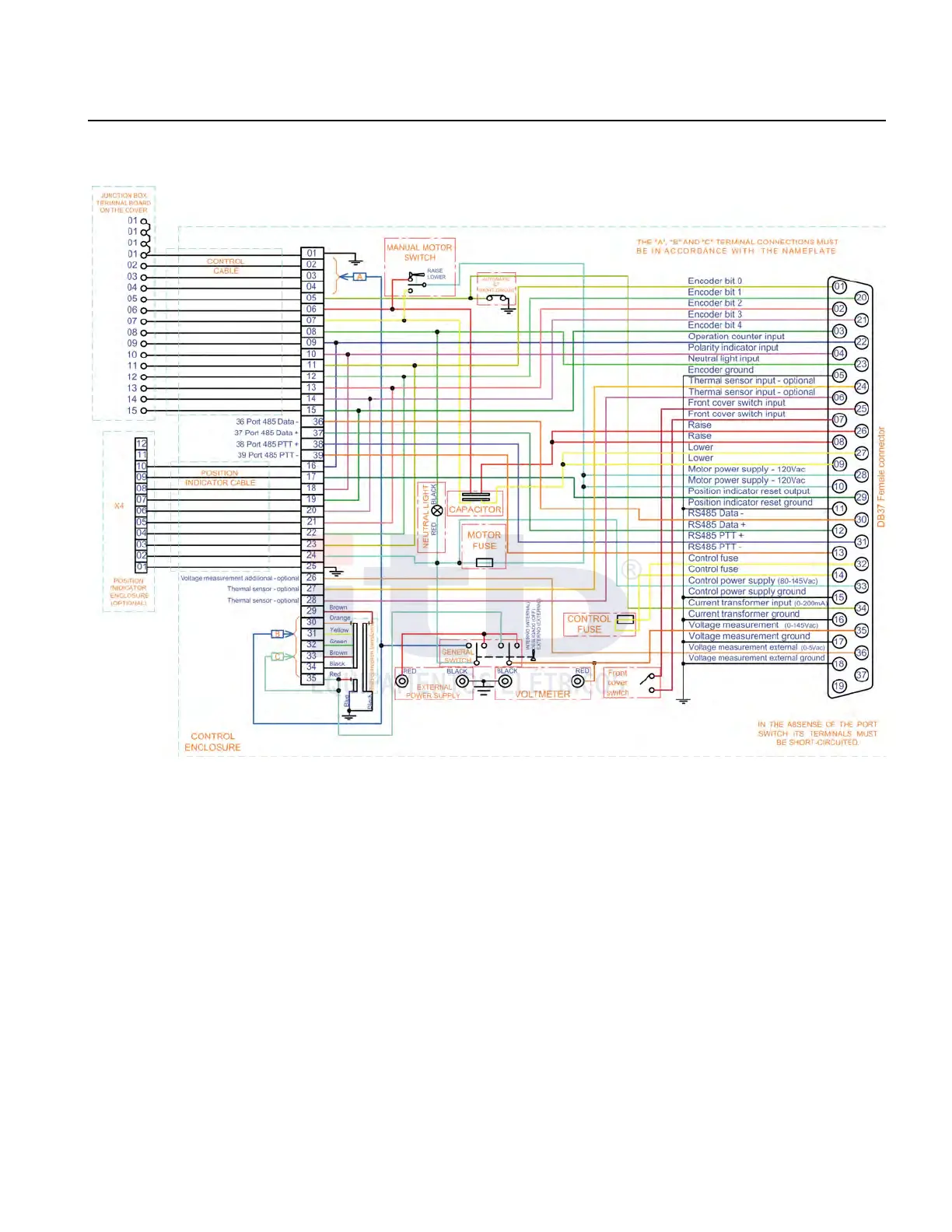
Figure 1 shows internal diagram and in figure 2, Control circuits general diagram is shown .
Measurements and analysis of line parameters are made by a micro-processed electronic monitoring device model
CTR-2, which automatically commands the on load tap changer and also adding other features such as position
indicator and data logger.
The voltage regulator is made of a single sealed tank with a pressure relief device, a visual oil level indication, top
connection for press filter, drain valve, device for collecting oil sample, anodized aluminum identification plate
engraved in low relief, external ZnO with polymeric encapsulation type serial arrester with mounted between
"Source" and "Load" insulators. Optional equipment include external tap changer position digital display, alternative
device for external on load tap changer actuation, oil temperature meter, additional external source meter Voltage
Transformer (VT) (0-5 Vac) or stainless steel identification plate can be supplied.
Power line connections are made through porcelain insulators with clamp type tinned copper connectors.
The actual tap is sensed by an encoder mounted integral with tap changer mechanism which by means of a BCD
code is digitally displayed on the LCD screen of the CTR2 control located inside the control box attached to the tank.
The neutral position indication is made by other equipment which is mechanically and electrically independent of the
position indication system and is displayed by a green LED type indicator on the bottom panel of the control box.
ITB - Equipamentos Elétricos Ltda.
Figure 2: Control general diagram.