Single Phase Voltage Regulator RAV-2
with control CTR-2
Instruction Manual MI-010
Page: 7/27
Rev. 06/2017
4. If the regulator remains stored for some time, check the dielectric strength of the oil as the NBR 6869. If the
resulting value is below 26 kV, treat the oil by and proceed to further analysis so as to verify its integrity.
CAREFUL: If active components need drying or its oil being heated, ensure that on load tap
changer does not receive temperatures above 90°C. This can cause damage to the switches
that are responsible for the operation, operation counter, polarity indication and confirmation
of nominal position. Conferir las demarcaciones de los aisladores en la tapa correspondiente a
los terminales del regulador.
5. Check the identification marking of the bushings on the lid correspondent to the terminals of the regulator.
6. Check the dielectric strength between the bushings and the tank using a 2.5 kV or higher insulation resistance
meter. This measurement must be performed after connecting shorted all bushings of regulator, measuring
between the tank and shorted bushings. The minimum value must be at least 10,000 megohms at ambient
temperature;
7. Check that voltage ratio reference for line voltage is properly inputed into the control of the regulator (see
parameter 32 of control settings);
8. Check if the CT is correctly programmed into the regulator control (see parameter 33 of control settings);
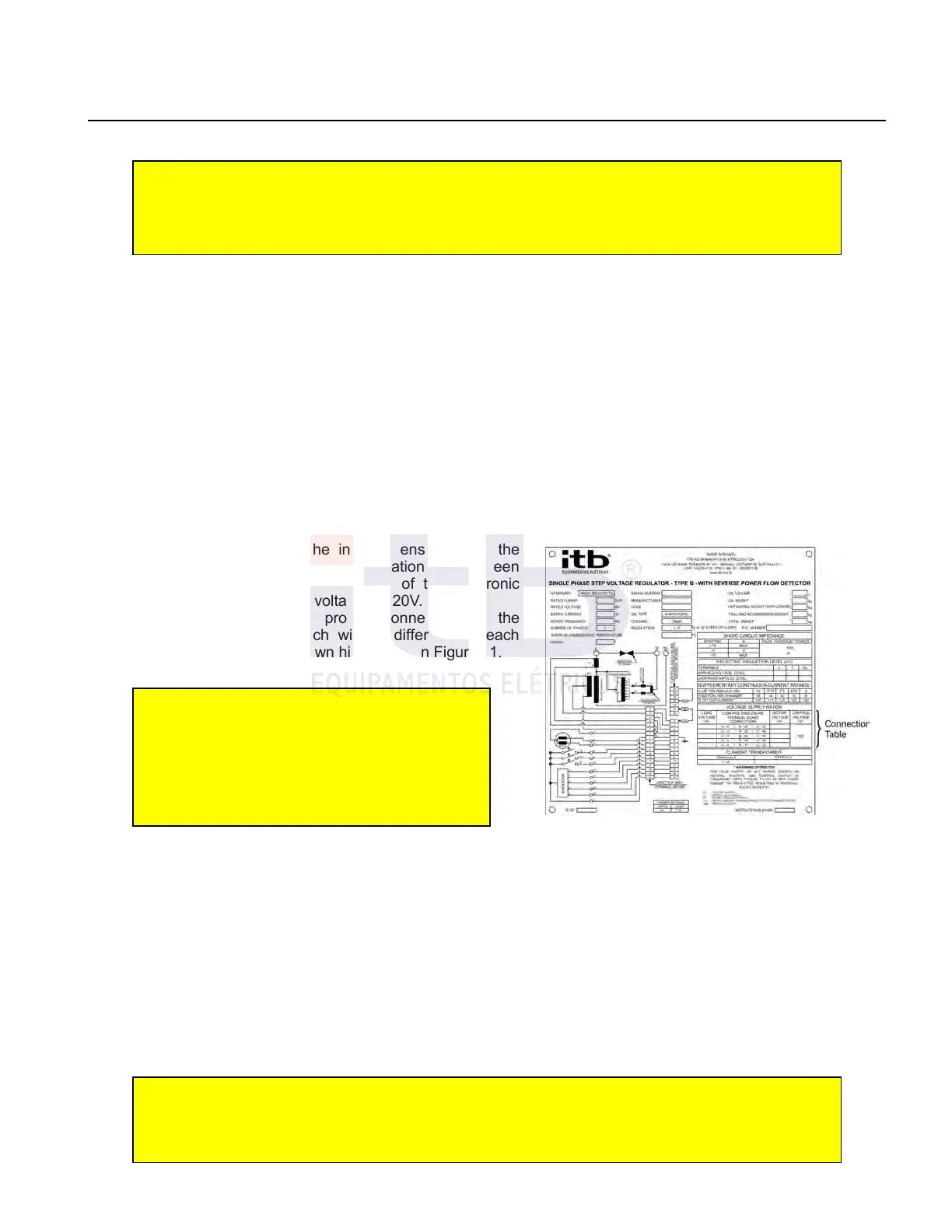
9. Check if the connections of the voltage transformer is suitable for the voltage of the network as indicated in
nameplate as shown in Figure 11.
HEIGHT
Regulators installed over 1000 above sea level have reduced nominal power as indicated in ABNT NBR EB 2108
and IEEE/ANSI C.57.15 standards.
Reference voltage
Most regulators can be used in systems with different nominal
voltages. It is necessary that the installer ensures that the
regulator is configured to maintain the relationship between
system voltage and the reference voltage of the electronic
control unit so that the reference voltage is 120V.
The nameplate indicates the proper connection of the
terminals "A", "B" and "C" which will be different for each
applicable system voltage as shown highlighted in Figure 11.
DANGER – Terminal “A” has to be
disconnected to manipulate terminals “B” and
“C” in secure conditions. Manipulating “B” and
“C” with terminal connected can cause electric
shock and short-circuit when regulator is
being fed by the high voltage terminal
It is important to note that the measurement will always be
made between the insulators "L" and " SL" and that
measurement shown as source is the voltage between " S " and " SL" which will be used as a reference in case of
reverse flow , excluding when caused by cogeneration , is calculated from the measurement of VT and the switch
position and, therefore , with accuracy of ± 1.5 % . For banks installed in closed triangle error may reach ± 6.5% , as,
beyond the own internal regulator error there is still a difference between the source and the load regulator
reference.
To measure with more accuracy, an additional external and independent VT should be used and the primary of the
VT which has to be connected between phases on the SOURCE side, and secondary , in which maximum voltage
cannot exceed 5VAC., must be connected to terminal block (input for external VT terminal) 26 of terminal blocks
located inside the control box ( this entry is optional for CTR -2 controls and must be requested when ordering ) and
grounding system taking care to establish the correct polarity to keep the same phase sequence used in direct flow
(Parameter screen 46 DEFVC ) and setting "1" option in voltage source metering on Source side ( screen parameter
47, OPMEDF ).
OBSERVATION1: Voltage on source side, as well as voltage of external Voltage Transformer,
won´t be available at the voltmeter terminals in the control cabinet, even when working in
inverse power flow.
ITB - Equipamentos Elétricos Ltda.
Figure 11: Nameplate