Function and Features
Copyright ©ITECH Electronic Co., Ltd. 26
NOTE
In order to ensure the stability of the system, using armored twisted pair cable between
the remote sense terminal of IT6900 and load.
Please note that the positive and negative polarity when wiring, otherwise it will damage
the instrument!
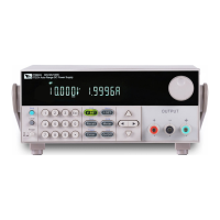
3.12.2 RS485 and Output Sync signal interface
Terminals on IT6922B/IT6932B/IT6933B/IT6942B/IT6952B/IT6953B power
supply rear board comprise Output Sync signal interface and RS485
communication interface, as shown below.
+,-: Output Sync signal terminal
A, B: RS485 communication interface
DC source output indication function:
There is a Output Sync terminal which is used to indicate the output state of DC
source at the rear panel. When in output on mode, Output Sync terminal will
output a high level. When in off mode, Output Sync terminal will output a low
level.
RS485 communication interface
RS485 communication interface is often used for multiple devices control.
Press
shift + I-set button to entry into the menu, user need to set the
parameters of Baud rate, Data bit, Stop bit, parity bit and address, the setting is
the same with RS232 communication setting.
3.13 Analog Control Interface
The IT6922B, IT6932B, IT6933B, IT6942B, IT6952B, IT6953B power supplies
have an external analog interface on the rear panel (see rear panel
introduction). The output voltage, current and ON/OFF can be controlled by
external voltage (0~10 V). If the user connects a voltage control device to
multiple power supplies, the output of multiple power supplies can be adjusted
simultaneously. External analog signals to control or monitor the output of the
power supply. Refer to the following diagram for the signal connections of the
analog interface.