User Guide
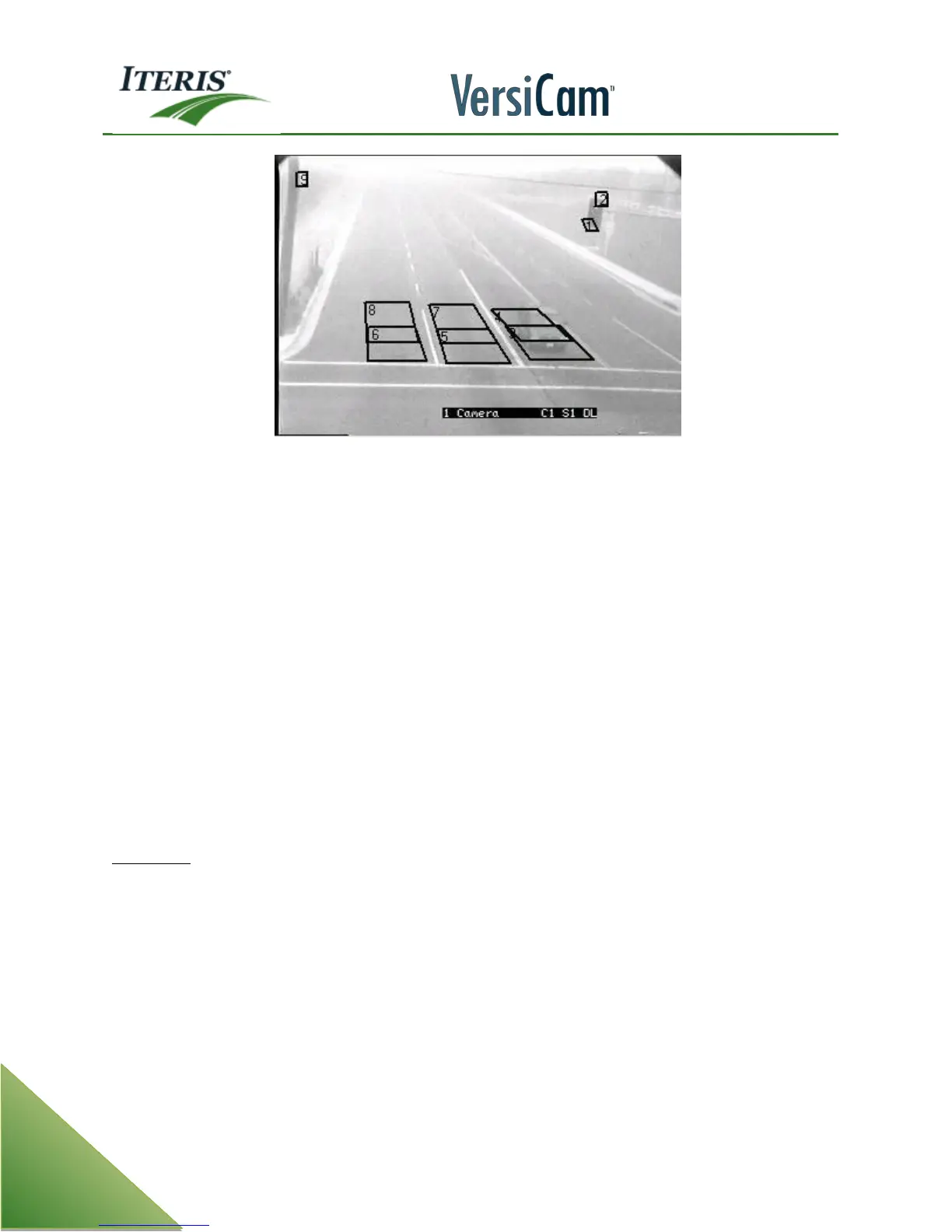
Improper Low Contrast (LC) Zone Placement
In the picture, the Low Contrast zones numbered one and two that are located on top of the signal head and
the LC zone number nine on the pole would all be poor choices for LC zone placement. Though these LC
zones meet the majority of the necessary criteria for LC zones including, correct size, they are located in the
top 1/3rd of the field of view, and they have been placed on an area of contrast; they fail the far field of view
test because both the signal head and the pole originate in the near field of view. Low Contrast zone
placement should not only be in the top 1/3rd of the FOV, but should also only be placed on objects that
originate in the far field of view. Objects in the near field of view will most likely always be clearly visible,
even in heavy fog. This improper LC zone setup and placement may result in the system not going into a Low
Contrast mode even when the conditions might benefit from this feature.
Note: It is also worth noting that this FOV is also very poor. It looks like there is probably horizon
included as part of the FOV, this should also be corrected.
"Low Contrast" zones are now an actual zone type. To create a Low Contrast zone, go to the ADD menu item
and select zone type "LC". LC zone parameters are automatically constrained, the system will only allow the
user to drawn them in the top 1/3 of the FOV and will restrict their size to less than 1/4 inch by 1/4 inch. This
was done in an effort help the user create effective LC zones that conform to the necessary requirements.
NONE (NO) - when a vehicle enters the zone area a call will not be placed. This type can be useful in
conjunction with the lane structure and LC and count zones.


 To Next Page