23
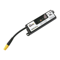
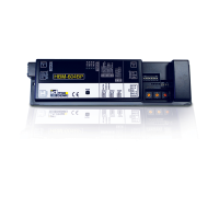
CBV30UserManual
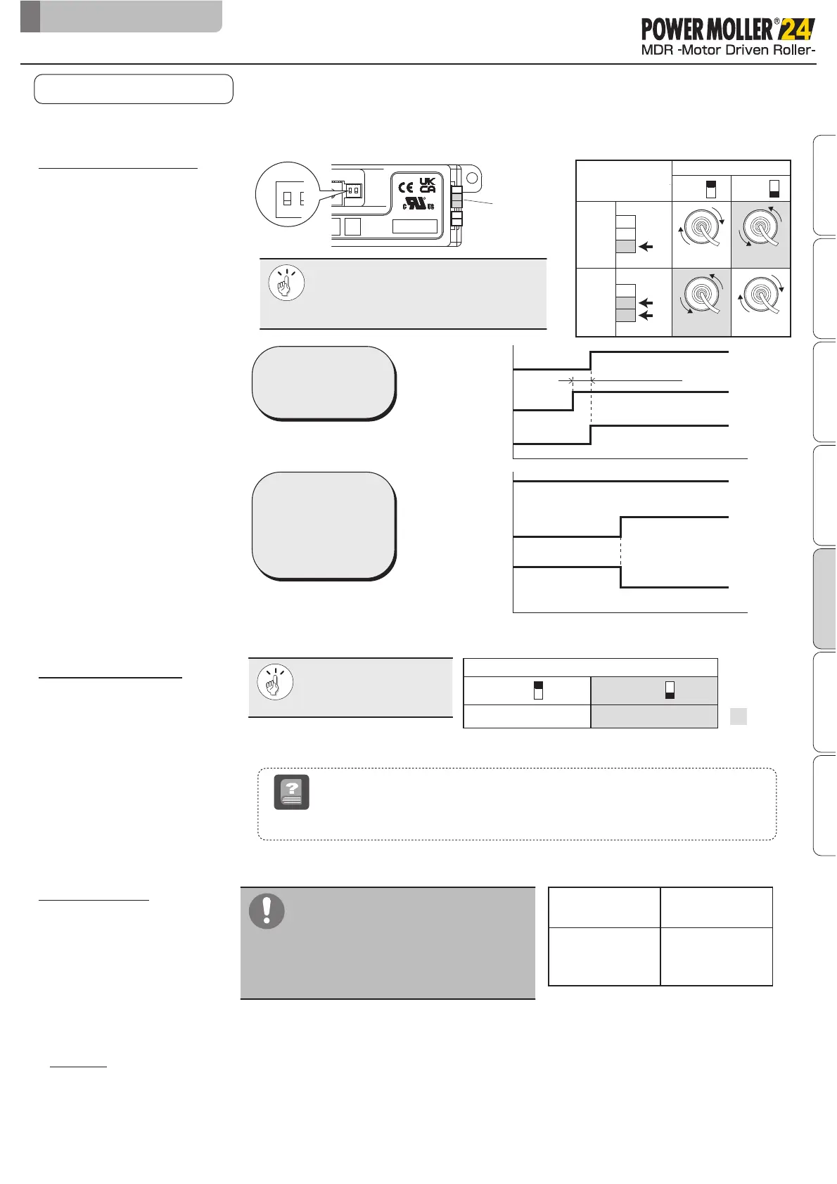
Change brake type by SW1#2
The MDR’s direction of rotation is determined by a combination of SW1#1 and CN2.
7-1.
Rotate direction setting
7. Control/Operation
Rotating
direction
*When SW1#1 is OFF
7-3.
STATUS signal
7-2.
Switching brake type
7-4.
Trial run
Make sure the other system is not operate.
Trays located in upstream may be transferred during trial run when the products are
installed conveyor line.
Make sure the other system is not affected by the products start running.
■
Connects a pull-up or pull-down resistor
within 25 mA or less.
Failure to follow this could result in damage
to parts/components inside the driver card.
■
When using multiple driver cards, connect
STATUS signal individually.
Make sure any wiring are connected correctly before trial run.
Safety precautions
Advance preparation
Check ProductInstallation/Wiring
Maintenance/Inspection
Specifications Control/Operation
100ms or more
Rotate direction setting
1
2
3
4
ED
2.BRK
1.DIR
R
INPUT:24V,1.6A
OUTPUT:24Vp-p,1.4A
3∅,194Hz(0Hz〜199Hz)
■
The transfer direction cannot be
changed using
SW1#1 while the MDR is running.
Change the direction when the MDR
stops.
■
SW1#2 is OFF
(Short circuit brake)
in factory setting.
The STATUS signal is output from CN2#3. (When normal output)
ON
SW1#1
OFF
CW CCW
CCW
CW
123
CN2#
123
CN2#
IN
IN
ON
Servo brake Short circuit brake
SW1#2
OFF
RUN
STOP
ON
OFF
CN2#2
CN2#1
CCW
CW
RUN
STOP
RUN
STOP
ON
OFF
CN2#2
CN2#1
MDR
12 123
CBV30-UL-N CBV30-UL-P
NPN
open drain
output
PNP
open drain
output
●
●
・When the brake is enabled, MDR will return to the originally retained position even if is forcibly
turned by external force.
・This can be used in places subject to external force when the MDR stops, such as ascending or
descending slope line.
Servobrake
term
Signal input to
CN2#2
Switching the
direction of rotation
while the MDR is
rotating by operating
CN2#2
* Servo lock brake is effected after short-circuit brake while
MDR stops.
*
CN2
OFF
ON
SW1#1
Factory
setting