Section 5, Installing Fan Heaters
5-2 Installation Manual for Oasis SCH33 Heating System
5.2 Fan System Operation
ITR fans consist of a 12 VDC brushless fan and heater coil
similar to a radiator.
When the heating fan comes on, the fan draws ambient air
from the interior, blows it across the heater coil and back
into the interior through a vent. The movement of air into
and out of the fan must not be obstructed. Reducing the
supply air (draw) to the fan will proportionally reduce the
flow of heated air.
Features
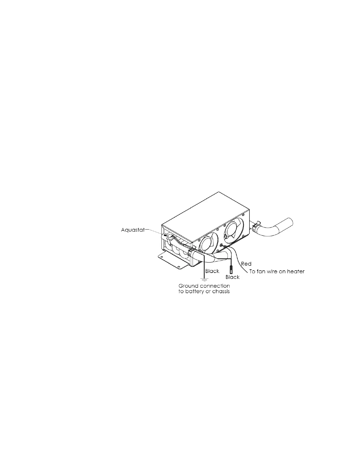
• ITR heating fans can be supplied with an aquastat, which
prevents the fan from operating and blowing cold air when
the system heat transfer fluid is below 120°F (49°C).
Figure 5-1 shows how to wire up the aquastat.
Figure 5-1: Wiring the Fan’s Aquastat
• If a “passive” radiant heat system is desired (i.e.,
baseboard or fin and tube configurations), consult ITR
for recommended installation procedures and design.
Multiple Zone Heating
Up to four thermostats (positive DC compatible) can be
installed to allow separate temperature regulation of the four
zones. The current draw for each zone is limited to 5 Amps.
The Zone control board has a 10 Amp draw limit for all the
fans across the four zones.
For larger current draw installations, contact ITR.