Section 10. Troubleshooting CHAPTER 5
TROUBLESHOOTING
International Thermal Research
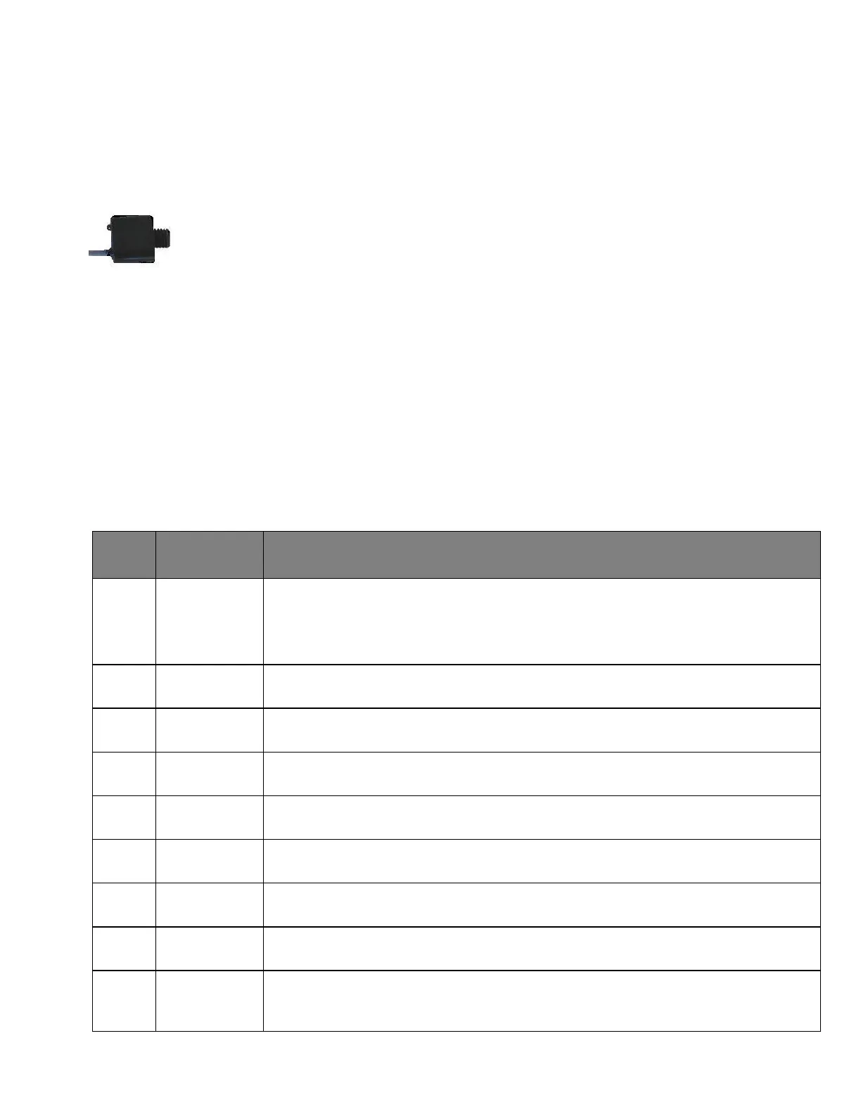
10.19 Flame Sensor Module
The Flame Sensor consists of a sealed module with a photodiode
aimed at the flame, a red LED indicator light and 3 wires, red (+),
black (-), and yellow (signal) connected to the main board. Under
normal operating conditions whenever the burner ignition begins,
the red LED will flash once indicating the red and black wires are
connected and the module is receiving power and working
properly. Once the burner is ignited, the LED will begin to flicker
like the flame. If for any reason the flame is extinguished, the
flickering will stop and the board will shut down the heater.
If the yellow (signal) wire is disconnected, the board will shut
down. If all the wires are properly connected with module flashing
and the board still shuts down, diagnostic code 7 Flame Out, the
board may be defective.
10.20 Test Points
The test points on the electrical control board allow for testing and
troubleshooting of the ITR heater’s electrical system. You will need
a voltage meter to plug into the test points.
Results / Optimal Condition
A voltage meter should show a voltage of about 2 volts if the flame sensor
detects a flame. If not, the voltage will be 0 volts.
An oscilloscope will show a 0 to 5-volt square wave with a frequency of
about 60 Hz, if the flame sensor is detecting a flame.
The voltage will be between 4 and 5 volts if the combustion fan is operating
correctly; 1 volt if the combustion fan is not drawing any current (open).
The voltage will be between 1 and 5 volts if the combustion fan is drawing
normal current, and 0 volts if the combustion fan is not drawing current.
The voltage should be between 4.8 and 5 volts. A lower voltage indicates a
problem with the voltage supply to the logic of the control board.
The voltage should be between 7.9 and 8 volts. A lower voltage indicates
a problem with the voltage supply to the logic of the control board.
This is the battery voltage supplied to the control board; it should be
between 11 and 15 volts.
The power to the flame sensor should read between 11 and 15 volts (same
as battery voltage).
The voltage will be between 4.8 and 5 volts if the heater is cycling (cycling
aquastat is open), and 0 if the cycling aquastat is closed.
The voltage will be 0 volts if an overheat condition is occurring or has
occurred in the past two minutes (overheat aquastat is open). The voltage
will be between 4.8 and 5 volts if the overheat aquastat is closed.