1. Trim the ERT module wires to 3.5 inches.
2. Carefully strip the insulation covering from the meter cable (purchased from the meter
manufacturer) approximately 1-1/2-inches from the end.
Caution: Do not cut through the individual wire insulation.
3. Separate the meter cable's black, white, and red wires for connection to the remote ERT module.
Cut off the unused wires even with the outer covering (insulation).
Caution: Do not strip the individual wires.
4. Connect the meter cable to the remote module wires using 3M gel-cap connectors following the
American RPM meter to remote ERT module wire connection information and wiring diagrams.
Important: Use a crimping tool compatible with gel-connectors. Do not use a standard pliers for
crimping gel-connects. For more information, see Using gel-cap connectors to complete wiring
connections on page 72.
Wire connection information
American meter wire Remote ERT module wire
Black Blue
White White
Red Red
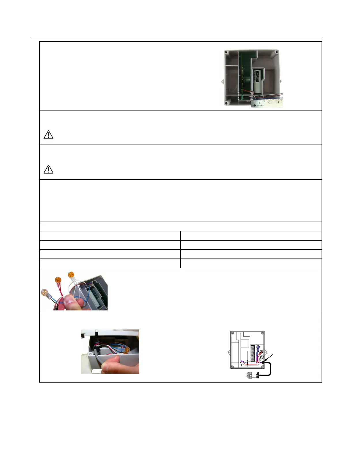
5. Insert the meter cable through the slot on the ERT module backplate. Install a cable tie to the
meter cable wire below the meter cable insulation to provide strain relief.
Specific Meter Manufacturer Installation
100G Series Gas ERT Module Installation Guide, Remote Mount TDC-0824-017 29
Proprietary and Confidential