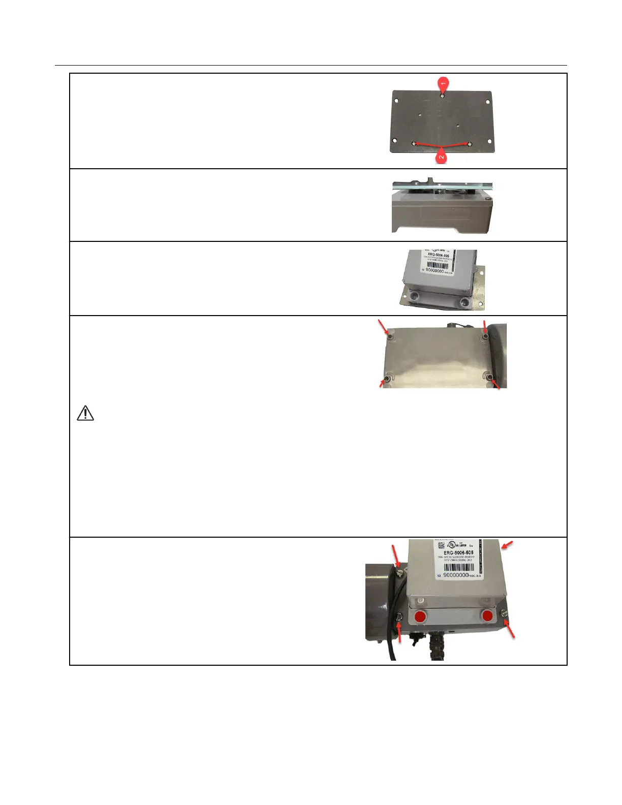
1. Insert the 8-32 x 7/16-inch screw (1) into the
top of the mounting bracket. Insert the two 8-32 x
3/4-inch screws (2) into the bottom of the
mounting bracket.
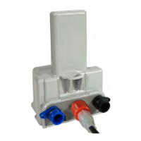
2. Insert one 3/32-inch nut on the top 7/16-inch
bracket screw (A). Slide the 100G series remote
gas module mounting lug over the top of the
bracket screw and nut.
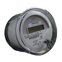
3. Secure the bottom 100G series remote gas
module mounting holes over the two 8-32 x 3/4-
inch screws with the remaining two 8-32 nuts.
4. Insert the #10 spacers into the four mounting
holes on the back of the IMC\W2.
Caution: Upright vertical positioning is very important because the remote module is:
• designed with the antenna in a vertical direction so the antenna is parallel to the reading
device (which has a vertical antenna). Matching antenna polarity can greatly affect RF
performance and enable easy ERT module reading.
• designed so the tilt tamper is vertical. It is important to maintain vertical positioning in
the field to enable tilt tamper stability.
• designed for installation with the batteries vertical (installed with the positive terminal
upward). Any other installation orientation will compromise battery life.
5. Secure the ERT module/bracket assembly on
the IMC\W2 using four ERT module/mounting
bracket screws (M6 x 20 mm). Install tamper
seals as required.
Specific Meter Manufacturer Installation
100G Series Gas ERT Module Installation Guide, Remote Mount TDC-0824-017 35
Proprietary and Confidential