GE supplied cable that connects to a B3,
LMMA, IMC/W2, or MC2
ERT module
Blue Blue
White White
Red Red
Pulse output Wire Pulse output 1 only Pulse output with 1
fault
ES3 or ETC ERT module
Output 1+ White White and blue White
Output 1- Black Red Red
Output 3+ Red White
Output 3- Green Blue
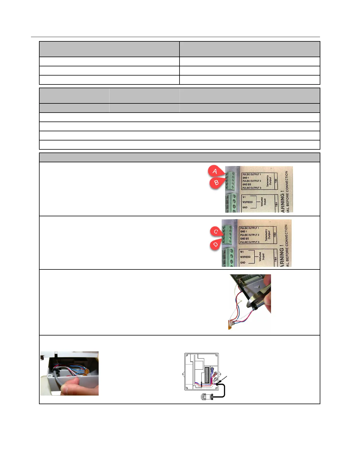
Wiring for direct connection to the IMC/W2
To receive uncorrected reads: Connect the red
wire to terminal block 3 (TB3 telemetry output)
GND1 (ground) position (B). Connect the white
and blue wires to the pulse output 1 position (A).
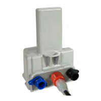
To receive corrected reads Connect the red
wire to the GND 2/3 (ground) TB3 telemetry
output position (C). Connect the white and blue
wires to the pulse output 2 position.
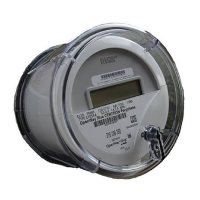
3. After completing the wiring connections, install
a cable tie to the meter cable just below the
exposed colored lead wires on the cable
insulation. Remove the excess cable tie using a
hand-held side-cutter pliers. The cable tie
performs as a cable strain relief to mitigate the
risk of destructive tension on the lead wires.
4. Tuck the three gel connectors and cable tie inside the module housing, as shown in the
placement illustration and schematic.
Specific Meter Manufacturer Installation
100G Series Gas ERT Module Installation Guide, Remote Mount TDC-0824-017 40
Proprietary and Confidential