Operation: CP1SD/T/L Version
CENTRON® Polyphase Meter Technical Reference Guide 75
Phase Voltage Deviation Check
Once every five seconds, the phase A voltage is combined with a user-defined percentage
tolerance (x) to determine the upper and lower bounds of the acceptable range for the other
voltages. The range of values for the percent tolerance is 1 to 25.
For Diagnostic #2 to pass, the following equations must be satisfied:
ACAc
ABAB
VxVVxV
VxVVxV
•−≥•+≤
•−≥•+≤
%)1(lower and %)1(upper
%)1(lower and %)1(upper
If the above equations are not met for three consecutive checks, the diagnostic check will
trigger. Although the meter is using VA as a reference voltage, it does not need to be correct
for this check to be valid. The percentage difference is the determining factor.
Diagnostic #2 Error Example
This example is for a Form 9S meter wired for a 277 Volt, 4-Wire Wye system, but the site
has an incorrect voltage transformer ratio. The meter was also programmed with a
percentage tolerance of 10%.
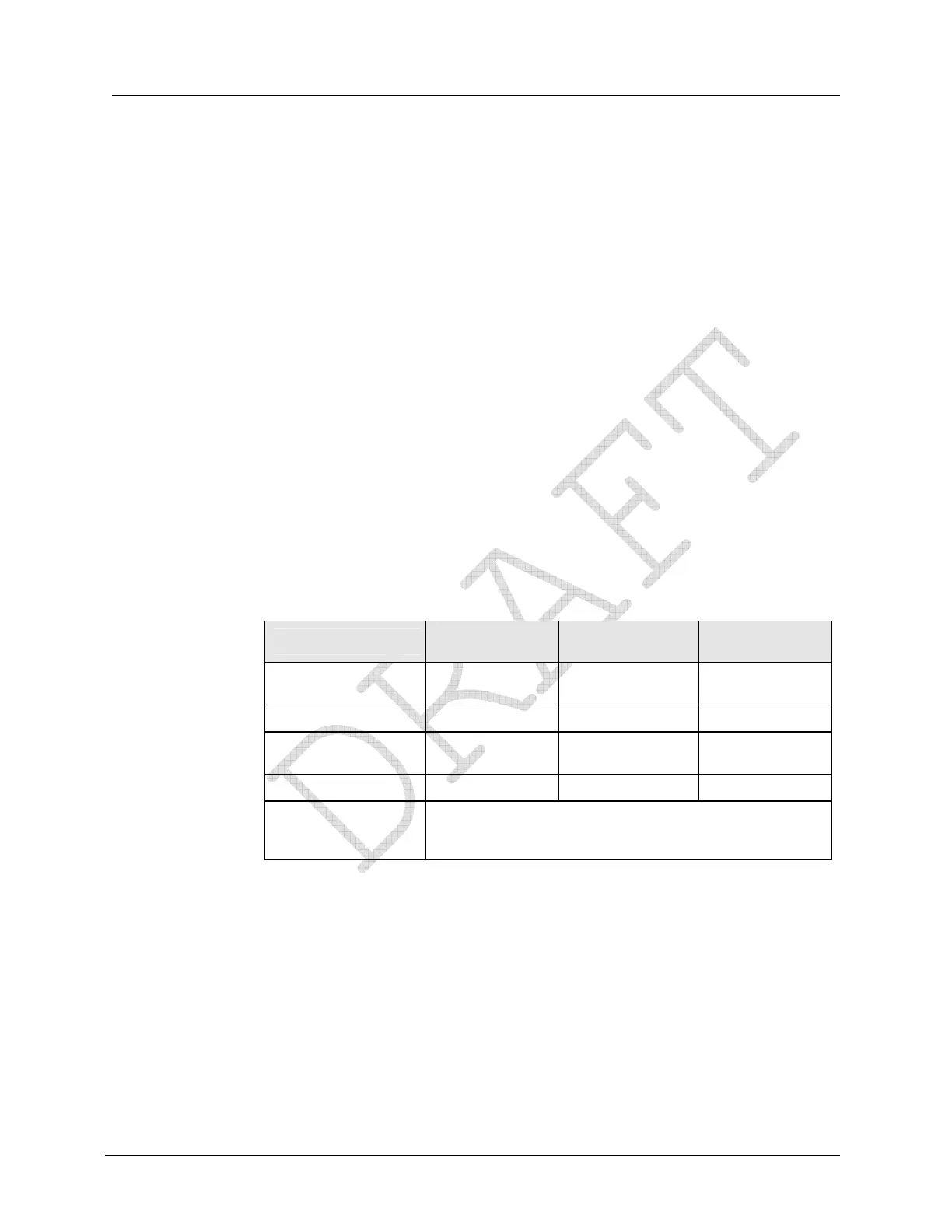
The following is the information from the SiteScan snapshot when the Diagnostic #2 error is
triggered.
Phase A Display
(Left Element)
Phase B Display
(Center Element)
Phase C Display
(Right Element)
Voltage Phase
Angles
PhA 0.0° V PhB 119.4° V PhC 240.9° V
Phase Voltage PhA 119.2 V PhB 275.4 V PhC 279.1 V
Current Phase
Angles
PhA 9.0° A PhB 125.5° A PhC 246.0° A
Phase Current PhA 6.8 A PhB 10.2 A PhC 9.8 A
Diagnostic Counters
d1 000
d2 001 d3 000
d4 000 d5A 000 d5B 000
d5C 000 d5T 000 d6 000
The second step to diagnose a Diagnostic #2 error is to compare the different phase voltage
readings. This can be done several ways by simply comparing the readings or plugging the
values into the equation. In this case, A phase is about 120 volts while both B and C phases
are about 277 volts. This could indicate an incorrect voltage transformer ratio or a shorted
voltage transformer winding for the A phase transformer. This could also indicate that A
phase is correct and both B and C phases are incorrect. Also note that diagnostic counter d2
has incremented to “001”.