Operation: CP1SD/T/L Version
CENTRON® Polyphase Meter Technical Reference Guide 79
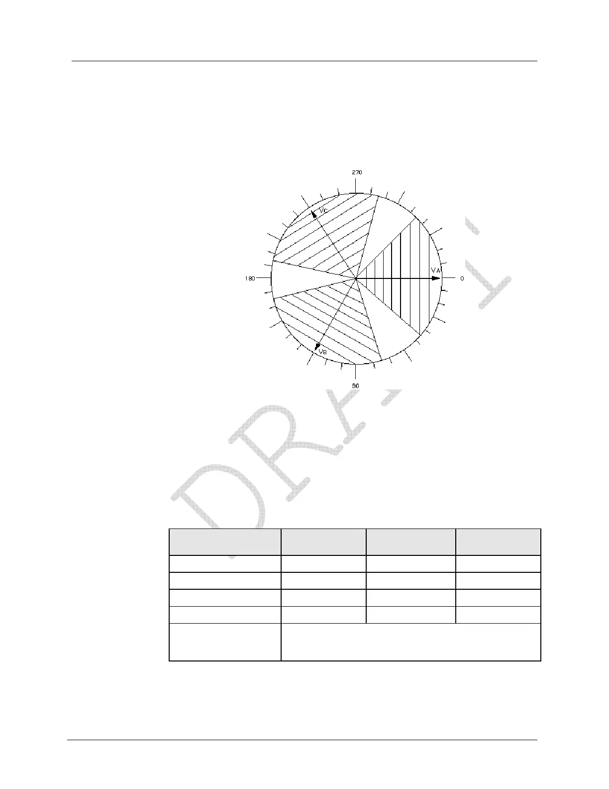
An example would be if a typical diagram has the C phase current angle at 240° and the user
has programmed an acceptable envelope of ±45° around that phasor, then the actual current
phasor must be between 195° to 285° from VA for the diagnostic to pass that check. The
system will check each current phasor in a similar fashion. Here, the current vector must be
within ±45° of the voltage vector for Diagnostic #4 to pass.
Figure 32: Envelope Example
Diagnostic #4 Error Example
This example is for a Form 9S meter wired for a 4-Wire Wye system with ABC phase
rotation, but the site has a poor load power factor condition. The meter was programmed
with a tolerance level of ±45° for Diagnostic #4 and Diagnostic #1 was also enabled and has
already passed.
The following is the information from the SiteScan snapshot when the Diagnostic #4 error is
triggered.
Phase A Display
(Left Element)
Phase B Display
(Center Element)
Phase C Display
(Right Element)
Voltage Phase Angles PhA 0.0° V PhB 120.4° V PhC 239.8° V
Phase Voltage PhA 120.8 V PhB 120.0 V PhC 119.3 V
Current Phase Angles PhA 2.0° A PhB 119.8° A PhC 297.2° A
Phase Current PhA 6.8 A PhB 10.2 A PhC 9.8 A
Diagnostic Counters d1 000 d2 000 d3 000
d4 001 d5A 000 d5B 000
d5C 000 d5T 000 d6 000