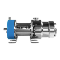
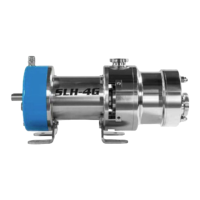
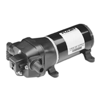
Automatic Water
System Pump
CAUTION
Not For Continuous Duty, Intermittent
Duty Only
Installation/Mounting
CAUTION
Installation Notes: To avoid the risk of fire. Be
sure that the area where pump is installed is isolated from gas,
fuel tanks, electrical wiring looms or flammable substances.
Failure to do so may cause injury or death.
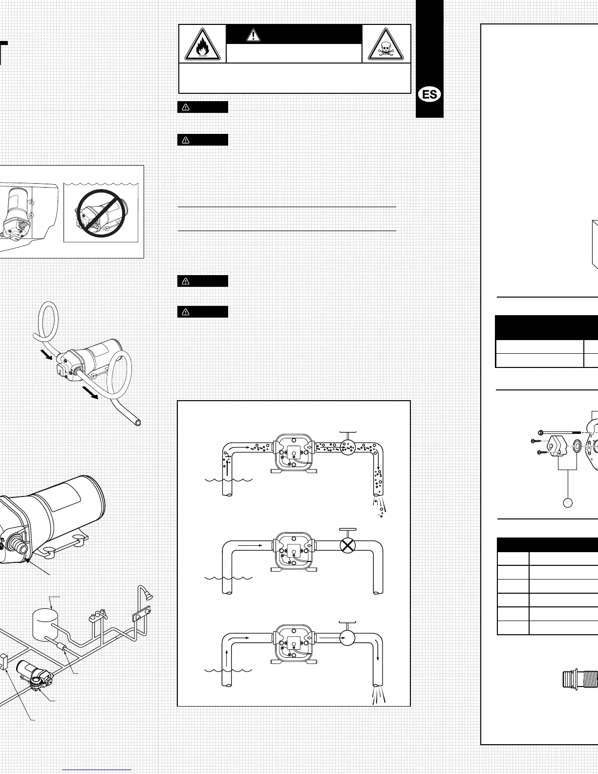
1: Select pump location. Pump
must be installed in a dry,
ventilated area.
2: Connect fittings supplied
with the pump to the vessels
plumbing. Use ½” (13mm)
I.D. flexible hose (preferably
braided or reinforced) to reduce
vibration through the plumbing
system (Figure 1). Use hose
clamps on the slip on barb hose
connectors.
Important: Install strainer pump inlet to
protect valves from debris.
3: Fasten pump to a flat surface. If mounting
vertically; install with pumphead down (Figure 2) Do not over
tighten screws to allow rubber mounts to absorb vibration.
4: Install inlet (A) and discharge (B) fittings. Firmly push slide
clips (C) forward to lock fittings in place. – Figure 3
Fuse
Figure 3.
Inlet Strainer (A)
Discharge (B)
KEY Description QTY Kit no
1 Upper Housing 1 18910-4060
2 Valve Kit 1 18911-7030
3 Diaphragm Kit 1 18912-3040
4 Lower Housing Kit 1 18915-9002
5 Pressure Switch 1 18916-0060
6 Service Kit 1 18920-9043
KEY Description QTY Kit no
7 Motor - 12 1 18753-5236
Motor - 24 1 18753-5237
8 Slide Clips 1 30648-1000
9 Pumphead Assembly 1 18914-6330
10 Pumpgard Strainer 1 46400-9500
30649-1000 30654-1000 30653-1000 30650-1000 30655-1000 30651-1000 30642-1000
PRECAUCIÓN
SI NO ESTÁ FAMILIARIZADO CON LAS NORMAS
ELÉCTRICAS APLICABLES, HAGA QUE UN ELECTRICISTA
CALIFICADO INSTALE LA UNIDAD.
PRECAUCIÓN
Se provee información del cableado sugerido como referencia.
Para más información, consulte las directrices de la norma
E-11 del ABYC, “Sistemas Eléctricos de CA y CC Instalados en
Embarcaciones”.
Tabla de tamaños de cables
Longitud total del cable – pies (metros)
Voltaje de 0 - 20 pies 20 - 35 pies 35 - 55 pies
la bomba (0 - 6 m) (6 - 9 m) (9 - 12 m)
12 VCC Nº14 AWG Nº12 AWG Nº10 AWG
(2.5 mm
2
) (4 mm
2
) (6 mm
2
)
24 VCC Nº16 AWG Nº14 AWG Nº12 AWG
(1.5 mm
2
) (2.5 mm
2
) (4 mm)
PRECAUCIÓN
La carcasa del motor puede calentarse durante el
funcionamiento por períodos largos. El contacto prolongado con
la piel puede causar quemaduras.
PRECAUCIÓN
Instale un filtro en una ubicación accesible (para
inspección y limpieza) entre el tanque y la entrada de la bomba,
para proteger a la válvula contra la acumulación de desechos.
Operación
•Lleneeltanquedeagua
•Abratodoslosgrifos
•Enciendalabomba
NOTA: Espere un retardo de 10 segundos para el encendido.
•Cuandoelaguaestélibredeaire,cierretodoslosgrifos
empezando por el más cercano a la bomba (Figura 6)
Importante: No opere la bomba más de 15 minutos seguidos.
 Loading...