45
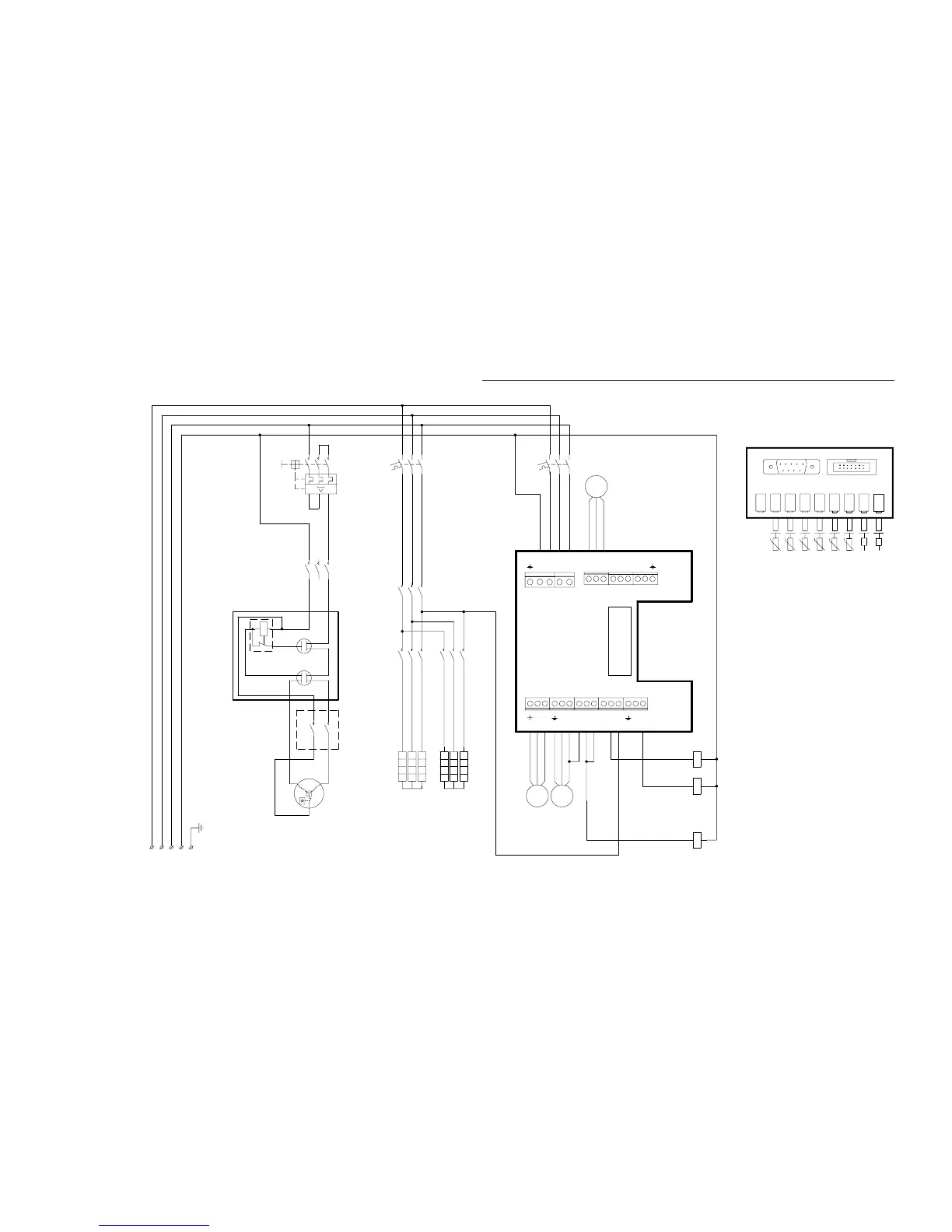
Circuit diagram Greenline C4 3x400V
Cr
R
2
1
5
Cs
*)
Sensor Board internal couplings
Givarkort interna kopplingar
Plintkort
Terminal card
Electric heater
9 kW ( 3kW+6kW )
Elkasset
Kompressor
*)
L2L1 L3 PEN
F1
12
34
56
MB1
NLN
MB2
LL
P3
P2 COMP
NL1
N
ELB
LLN
T1 T2
SV1VXV P1
CLOSE
OPEN
OPEN
NLNL2 L3
M M
P3P2
CK1
A1 A2
VXV
M
CE1
1
2
3
4
5
6
CE2
1
2
3
4
5
6
F2
12
34
56
ÖH
CE1
A1 A2
CE2
A1 A2
HP LPGT11VVP GT3 GT6 GT8 GT9 GT10
SERVICE J1
TS
C
MS
1N2N
S R
L1T1
Blue
Brown
CK1
1
2
3
4
5
6
Blue
Black
MB1
1
2
3
4
5
6
Driftkondensator / Run capacitor
Startkondensator / Start capacitor
Overheat cutout electric heater
Circuit breaker electric heater
Överhettningsskydd elkassett/
MS:
Mjukstart, tillbehör
Softstarter, accessories
Contactor electric heater 2
Kontaktor Elkassett 2/
Contactor electric heater 1
Contactor compressor
Kontaktor Elkassett 1/
Kontaktor kompressor/
Motor cutout compressor
Motorskydd kompressor/
Startrelä / Potential relay
Circuit breaker heatpump
Automatsäkring elkassett/
Automatsäkring värmepump/
R:
Cs:
Cr:
ÖH:
F2:
MB1:
CK1:
CE1:
CE2:
F1:
Pressotat låg/ Low pressure switch
Köldbärare ut/ Heat transfer fluid (coll) out
Pressostat hög/ High pressure switch
Köldbärare in/ Heat transfer fluid (coll) in
Värmebärare in/ Heat transfer fluid in
Värmebärare ut/ Heat transfer fluid out
T11
T6: Kompressor/ Compressor
T11:
LP:
HP:
T8:
T10:
T9:
Varmvatten/ Hot waterT3:
T3 T9T8T6 T10
Compressor
Power supply
Inkommande matning
3x400V+N+PE
Brown
Blue
Black
 Loading...