Do you have a question about the J.P. Instruments EDM-730 and is the answer not in the manual?
Table comparing features of EDM 730 and 830 models.
Overview of the EDM system's capabilities and technology.
Lists advantages of proper mixture control for engine efficiency and longevity.
Explains the temperature probes and their accuracy.
Describes how EGT relates to combustion and mixture control.
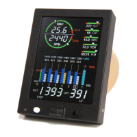
Illustrates the main display layout and its components.
Explains the automatic dimming feature of the display.
EGT columns indicate percentage of red line for comparison.
EGT columns normalized for trend analysis, showing changes.
How to set engine temperature units (Fahrenheit or Celsius).
Explains cylinder labels, I.D. boxes, and bar graph displays.
Displays %HP if relevant parameters are functional.
Provides expanded information for monitored parameters.
Bargraph display of hottest TIT, checks redline exceedance.
Digital and analog indications for parameters with pointers and ranges.
How EGT and CHT values are displayed in the Scanner Information Area.
Examples of EDM-830/730 display layouts in different orientations.
Depicts RPM and MAP graphically and digitally, with redline indicators.
Displays linear bar graphs with digital readouts for various parameters.
Describes EGT representation in bargraphs and digital values.
Describes CHT representation in bargraphs and digital values.
Describes TIT bargraph display and redline indication.
How to activate and use Automatic Mode for scanning.
How to activate and use Manual Mode for specific parameter monitoring.
How to activate and use LeanFind Mode for mixture leaning.
Instructions for mounting, button relocation, and display orientation.
Describes primary functions of the STEP button in different modes.
Details secondary functions of the STEP button, including alarm management.
Describes primary functions of the LF button, including mode switching and view toggling.
Details secondary functions of the LF button, primarily in pilot programming.
Explains combined functions of STEP and LF buttons for programming and mode changes.
Explains the content and function of the Scanner Information Area.
Describes the EDM's self-tests during startup and checks during flight.
Introduces the three operating modes: Automatic, Manual, and LeanFind.
How to activate and use Automatic Mode for scanning.
How to activate and use Manual Mode for specific parameter monitoring.
Explains ROP/LOP leaning methods and LeanFind initiation.
Step-by-step procedure for leaning the mixture Rich Of Peak (ROP).
Step-by-step procedure for leaning the mixture Lean Of Peak (LOP).
General explanation of leaning procedures, pre-leaning, and LeanFind initiation.
How EDM detects Rich of Peak and displays the result.
How to enrichen mixture to the desired ROP setting.
How EDM detects Lean of Peak and indicates progress.
How to adjust mixture to the desired Lean of Peak setting.
Detailed explanation of the Lean of Peak process and graphical depiction.
Specific leaning procedures for turbocharged engines.
Recommended setup and alerts for engine run-up phase.
Recommended setup and alerts for takeoff, climb, and full throttle.
Recommended setup and alerts for cruise phase.
Recommended setup and alerts for descent phase.
Explains shock cooling, its dangers, and how the EDM monitors it.
Common problems and corrective actions for EDM users.
Chart listing typical EDM indications and their meaning for engine problems.
Chart linking display symptoms to probable causes and recommended actions.
Explains programmable alarms, flashing indications, and remote outputs.
Lists the priority of different alarms when multiple occur simultaneously.
Explains combustion issues causing detonation and pre-ignition.
Explains the importance of accurate fuel flow measurement and the EDM's role.
Procedure for entering fuel added to the aircraft upon startup.
Illustrates refueling shortcuts for aircraft with internal tabs.
Illustrates refueling shortcuts for aircraft with main and auxiliary tanks.
Illustrates adding fuel for partial refueling.
How to manually reset the 'USED' fuel parameter to zero.
How to enable continuous accumulation of total fuel used.
Explains the three-position switch for selecting displayed parameters.
Lists scan sequence and parameters for systems with Fuel Flow Option.
Table detailing scanner parameters, examples, and switch settings.
Steps for downloading data from the EDM to a USB drive.
Steps for transferring downloaded data to a PC using EzTrends.
Instructions to enter Pilot Programming Mode for customization.
How to adjust the HP constant for aircraft-specific calculations.
How to calibrate the EDM's MAP reading to match the aircraft gauge.
How to calibrate the EDM for the factory original TIT probe.
Details the three settable parameters for the fuel flow option.
Explains the K factor and how to enter it.
Procedure to fine-tune the K factor based on actual fuel usage.
Setting to display total fuel used for extended trips.
Selecting the format for EDM fuel data output to GPS.
Setting date, time, and user ID for long-term data memory.
Table of default alarm limits for various parameters.
Procedure to change alarm limits or set usable fuel capacity.
Setting fuel units, main/aux tank capacity, and alarm limits.
Setting engine type, recording mode, data rate, cylinders, HP, EC.
Customizing display preferences and backlight intensity.
How to exit the programming mode.
Setting MAP overboost redline and selecting fuel flow units.
Setting main tank capacity, low time, and low fuel alarms.
Selecting engine filter based on carbureted or injected type.
Setting cylinder count for RPM calculations, with exceptions.
Adjusting rated HP and engine constant for HP calculations.
Steps to initialize or change tank capacities.
Explains GPS data formats for compatibility with EDM.
Selecting EDM output format for GPS fuel data communication.
Tables of messages indicating fuel flow or GPS signal problems.
Details data input formats and ports for GPS communication with EDM.
Pin assignments for EDM connectors to various sensors and GPS models.
Specific interface connections for popular GPS models.
How to customize linear gauge layouts and display preferences.
Lists general reading materials for pilots.
Lists advanced references for those with engineering backgrounds.
Provides contact information for JPI technical support.
Details the warranty terms and conditions for JPI products.
Highlights key differences for twin-engine setups.
Reminders for installation requirements specific to twin engines.
Alphabetical index of topics covered in the manual.
Quick guides for Normalize/Percentage Views, Auto Scan, and parameter exclusion.
Quick guides for changing scan rate, resetting fuel, transferring data, and initializing tanks.
Procedures for entering fuel amounts for filled or added/removed fuel.
How to perform temporary or flight-remainder alarm resets.
Quick guide for Rich of Peak leaning procedure.
Quick guide for Lean of Peak leaning procedure.
Monitors and displays fuel pressure, amperage, and tank levels with alarms.
Displays engine running time (HOBBS) and current time.
Displays and controls a timer function.
Adds HOBBS display to pilot program mode options.
Adds options for Amps, Fuel Pressure, Fuel Levels, etc., to factory limits.
Pin assignments for the Amps harness.
Pin assignments for the Fuel Pressure harness.
Pin assignments for Fuel Level harnesses.
| Display Type | LCD |
|---|---|
| Fuel Flow | Yes |
| Oil Temperature | Yes |
| Oil Pressure | Yes |
| Volts | Yes |
| Outside Air Temperature (OAT) | Yes |
| Operating Temperature | -20°C to 70°C |
| Storage Temperature | -55°C to 85°C |
| Mounting | Panel mount |
| Certification | TSO'd |
| Type | Engine monitor |
| EGT Probes | 4 |
| CHT Probes | 4 |