For Your Safe Flight Page | 37
Section 7 - Alarms
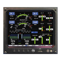
Whenever a measured parameter falls outside of the normal allowed
operating limits, i.e. goes beyond redline, the main display will blink an
ALERT icon in red paired with that parameters current digital value and a
flashing red label (i.e. CHT) will appear in the Scanner area and the
RAD. For example, if CHT 2 is at 480, and redline is 460, it would be
displayed as 480 CHT (CHT flashes in red). Other alarm examples are:
2780 RPM, 15 O-P, 34 F-P, 240 O-T.
Tapping the CLEAR button extinguishes the alert for ten minutes
whereas holding the CLEAR button turns the alarm off for the remainder
of the flight.
Primary alarm limits for each specific aircraft model are set by JPI in
accordance with the Pilot Operating Handbook and/or TCDS and are
not programmable by the pilot. These typically include some or all of
the following measurements: CHT, CDT, O-T, O-P, F-P, GAL LEFT, GAL
RIGHT, MAP, RPM, FF, IAT, CRB, and TIT. To view the alarm limits
screen, hold button 2 during power up (or hold both buttons 2 & 3 during
normal operation), tap NEXT until the list is displayed.
The primary functions for your installation are shown on the Primary label
on the back of the instrument and are identical to those specified in the
FAA Approved Airplane Flight Manual/Pilot’s Operating Handbook.
Non-primary Alarm Priority
Primary alarms will always have precedence over non-primary alarms.
The typical non-primary alarm priorities are as follows:
Highest ........................................................................................... Lowest
MIN REM DIF CLD BUS H BUS L AMP