19
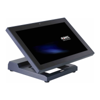
3. Next step is to route any cables you
need to go to the system as
required. A space is provided just
by the power supply for the cable to
exit cleanly, assuming they are
routed via the swing arm cable
channel as in a normal install.
Cables can also be routed down as
well. Be sure cables are clear or
protected of any sharp surfaces. You
can remove the system on and off
the wall mount bracket as needed to
route the cables.
4. Cables can exit the top or bottom
when routed between the bracket
and system. A wall hole could be
used to cover the cables in the
power supply area.
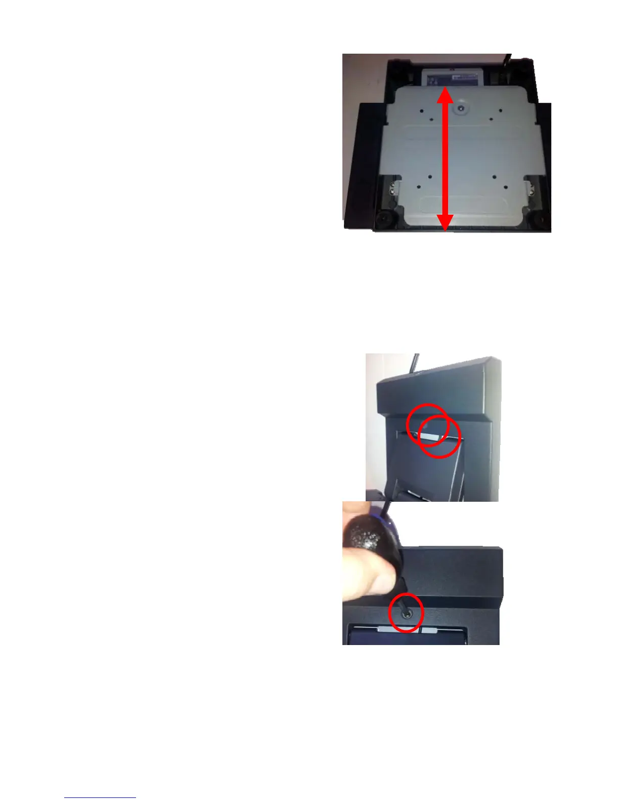
5. The final step is to install the locking
safety screw. This screw is to
insure the system is not knocked of
the wall by accident . The 4 mm
screw supplied is used for this
propose. First remove the rubber
hole plug from the system, then
screw in the safety screw. The
system is now secure enough and
the swing base can be adjusted to
the desired viewing angle.