22
Bit 7: Cash Drawer 2 pin output control
Bit 6: Reserved
Bit 5: Cash Drawer 2 pin input control
Bit 4: Cash Drawer 1 pin output control.
= 1: Opening the Cash Drawer
= 0: Allow close the Cash Drawer
Bit 3: Cash Drawer 1 pin input control.
= 1: the Cash Drawer closed or no Cash Drawer
= 0: the Cash Drawer opened
Bit 2: Reserved
Bit 1: Reserved
Bit 0: Reserved
Note: Please follow the Cash Drawer control signal design to control the Cash
Drawer.
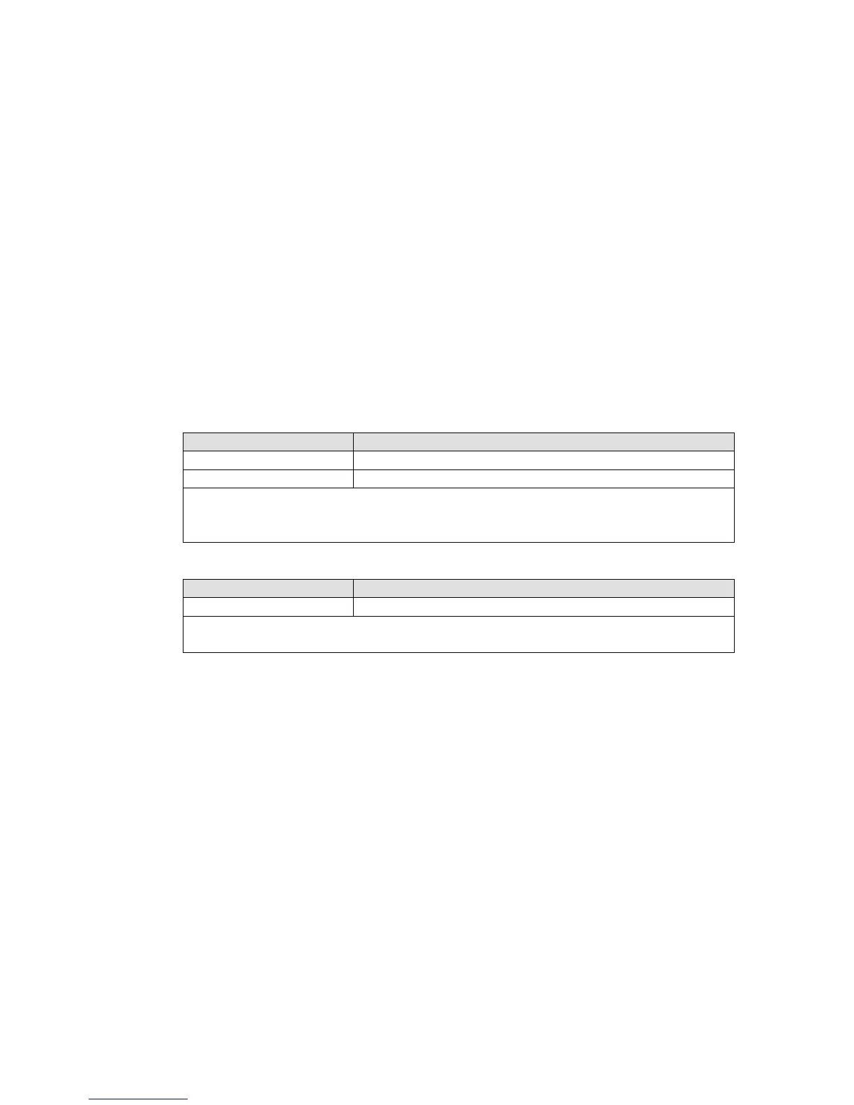
Cash Drawer Control Command Example
Use Debug.EXE program under DOS or Windows98
Command Cash Drawer
=1 for opening Cash Drawer by “DOUT bit0”
pin control.
Set the I/O address 482h bit4 = 0 for allow close Cash Drawer.
Command Cash Drawer