GENSET AND BATTERY PACK
4271491-Second Edition 3-27
3
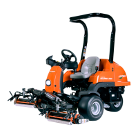
35. Remove screw (47) and lock washer (48).
36. Remove screw (43), lock washer (44), and flat
washer (45), and remove air deflector (46).
37. Remove three screws (41) and lock washers (42),
and remove the screen holder (49).
Figure 3-43
38. Remove screw (51), lock washer (52), and flat
washer (53).
39. Repeat step 38 for other side of machine, and
remove crossmember (50).
40. Remove throttle actuator. (See “Throttle Actuator
(Diesel Models)” on page 3-20.)
41. Remove fuel pump. (See “Fuel Pump (Diesel
Models)” on page 3-23.)
42. Remove fuel shutoff solenoid. (See “Fuel Shutoff
Solenoid (Diesel Models)” on page 3-23.)
43. Remove alternator. (See “Alternator (Diesel Models)”
on page 3-16.)
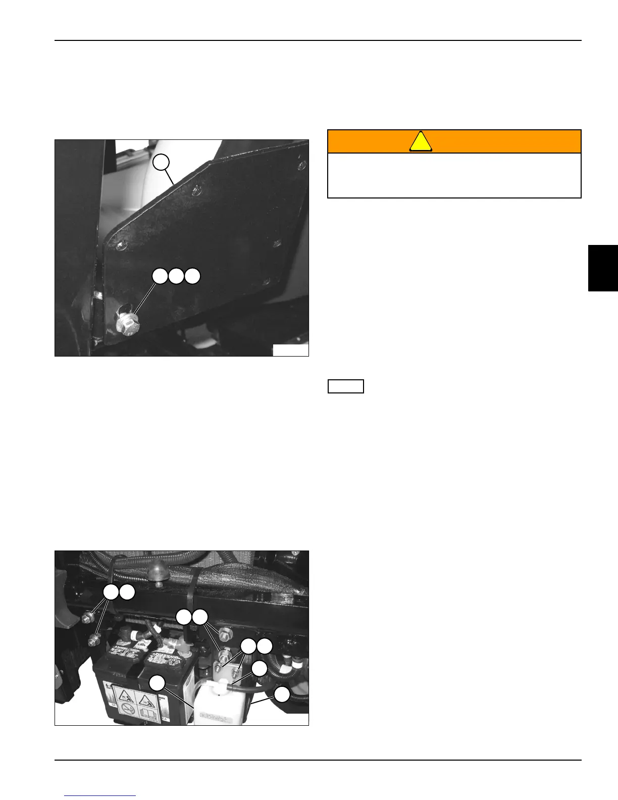
Figure 3-44
44. Tag and disconnect hose (58) from radiator overflow
bottle (60). Cap fitting and plug hose to prevent
leakage and contamination.
45. Remove nuts (56), screws (57), and radiator overflow
bottle (60).
46. Using an engine hoist, support the genset (59), and
remove nuts (54) and genset carrier mounting
screws (55).
47. Remove the resistor bank assembly and jumper
harness. (See “Resistor Bank Assembly and Jumper
Harness” on page 4-165.)
48. Repeat step 46 for other side of machine.
49. Check for any connected wires and components, and
carefully remove the genset from the machine.
50. Place the genset on a suitable stand or workbench
that will support the full weight in a safe manner while
preventing damage to the genset.
If the engine is being replaced, some components must
be removed and installed on the new engine. See the
“Parts and Maintenance Manual” for additional
information and illustrations.
TN2715
5756
58
60
54 55
54 55
59
Prevent personal injury. Use a properly rated
lifting device. Always be sure the load is
balanced before lifting.