GENSET AND BATTERY PACK
4271491-Second Edition 3-35
3
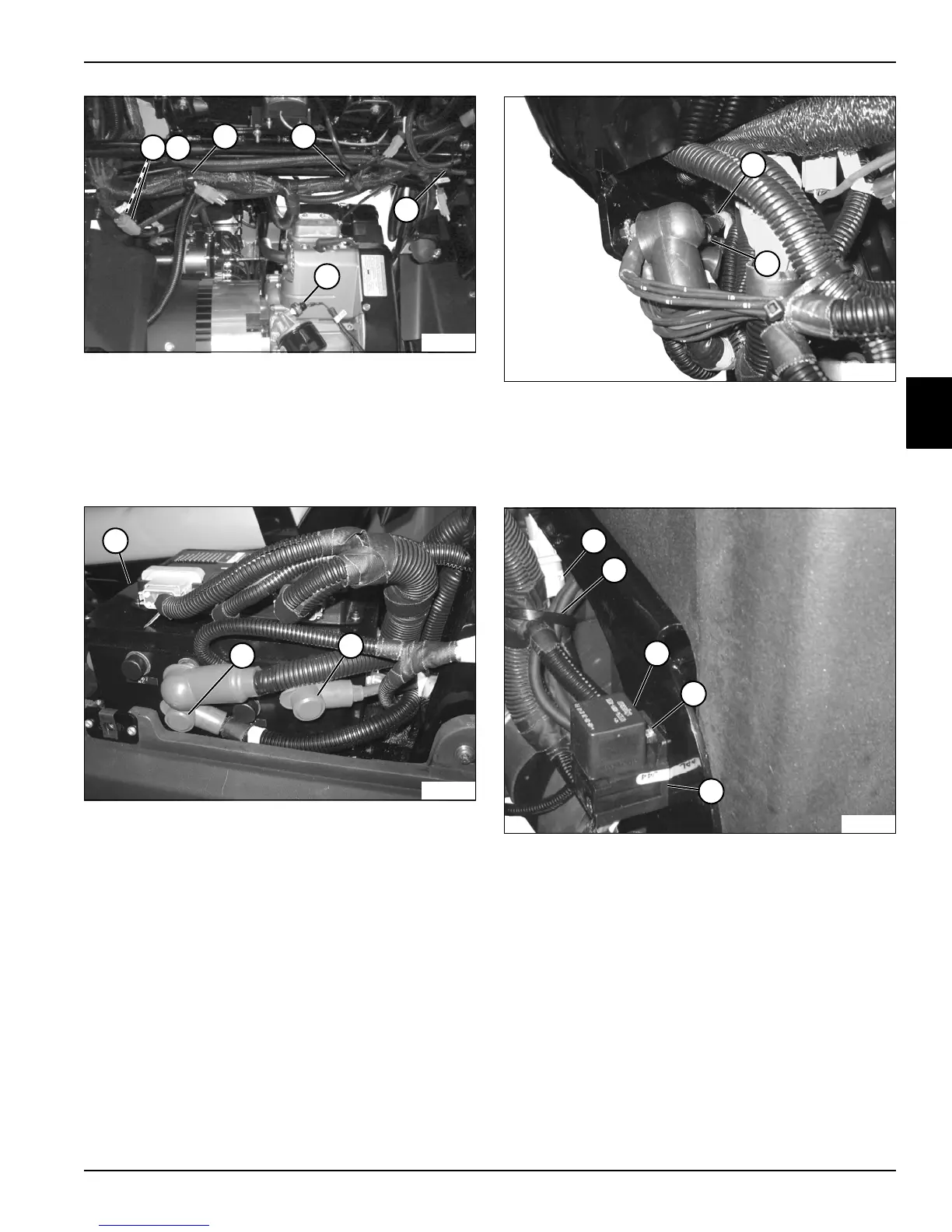
Figure 3-55
14. Tag and disconnect genset-to-main harness
connectors (1 and 2).
15. Cut cable ties (3).
16. Tag and disconnect oil pressure switch connector
(4).
Figure 3-56
17. Tag and disconnect the generator positive (+) output
cable (6) and 12 VOLT POS connector (7) from PDU
(5). Carefu lly guide the cables away from the PDU
and position the cables to be unrestricted during
genset removal.
Figure 3-57
18. Tag and disconnect the generator negative (–) output
cable (8) from ground stud (9). Carefully guide the
cable away from the frame and position the cable to
be unrestricted during genset removal.
Figure 3-58
19. Tag and disconnect rectifier connector (10).
20. Cut cable tie (11).
21. Remove fan relay (12).
22. Remove screw (13) and fan relay base (14).