ENGINE
4234520 First Edition 3-13
3
Throttle Cable and Control Lever
Removal and Installation
See Figures 3-18 through 3-21.
1. Park the mower safely. (See “Park Mower Safely” on
page 1-6.)
2. Remove the instrument panel. (See “Instrument
Panel” on page 4-103.)
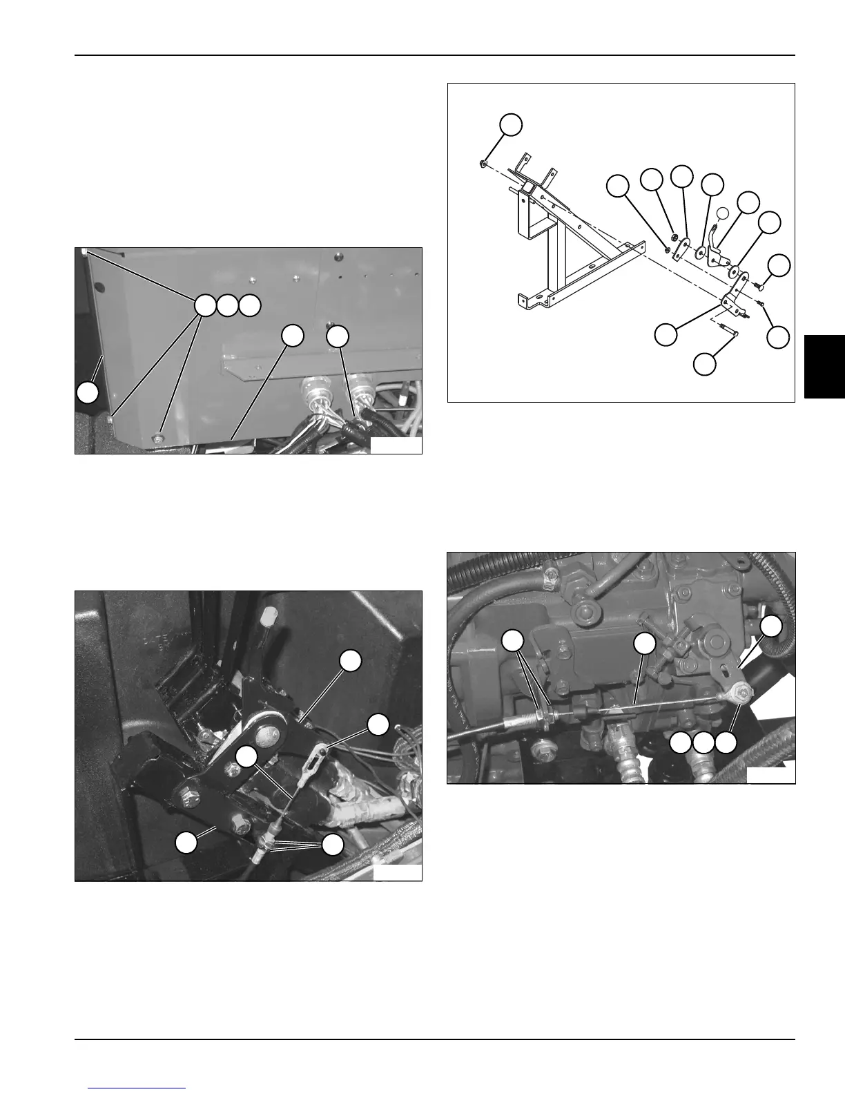
Figure 3-18
3. Remove three screws (1), lock washers (2), and flat
washers (3)
4. Remove seal bracket (6).
5. Loosen screw (5) and move console wall (4) inward
to allow access to throttle cable and control lever.
Figure 3-19
6. Remove palnut (8) and disengage throttle cable (11)
from throttle handle (7).
7. Loosen nuts (9) and disengage throttle cable (11)
from throttle lever mounting bracket (10).
8. Slide throttle cable through frame.
Figure 3-20
9. Remove two flange nuts (12) and screws (20).
10. Remove throttle lever mounting bracket (21), and
disassemble lock nut (13) and screw (19), lock nut
(14) and carriage bolt (18), friction plate (15), two
friction discs (16) and throttle handle (17) from
throttle lever mounting bracket.
Figure 3-21
11. Remove nut (25), washer (26), and screw (27) to
disconnect the throttle cable (23) from the governor
throttle lever (24).
12. Loosen nuts (22) and remove throttle cable.
Installation Notes
• Install the throttle cable and control lever by reversing
the order of removal.
• When replacing a worn or broken throttle cable, route
the same as the old cable.
• After replacing, follow the adjustment procedure.
(See “Throttle Cable” on page 3-5.)
13
12
14
15
16
17
19
TN2298
16
18
20
21

 Loading...