- 14 -
G31 Series User's Manual
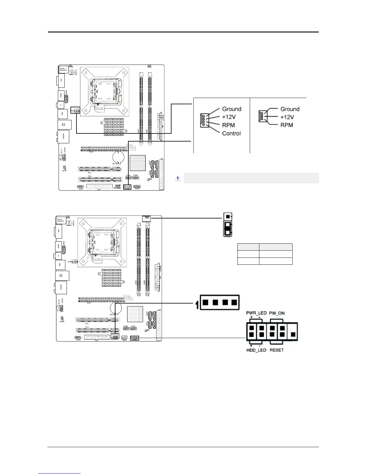
3.4 FAN Power Connectors
These connectors each provide power to the cooling fans installed in your system.
CFAN or CFAN1: CPU Fan Power Connector
SYSFAN1: System Fan Power Connector
SYSFAN2: System Fan Power Connector (Optional)
3.5 Front Panel Switches & Indicators Headers
1
SPEAKER
HDD_LED (Hard Driver LED Header)
Connect the HDD LED cable to these PINs, in order to see the HDD status
RESET (Reset Control)
This connector connects to the case-mounted reset switch for rebooting your computer
without having to turn off your power switch. This is a preferred method of rebooting in
order to prolong the lift of the system’s power supply.
PWR-ON (Power Button)
This connector connects to the case-mounted power switch to power ON/OFF the system.
SPEAKER (Speaker)
This 4-pin connector connects to the case-mounted speaker. You should follow the
instruction of the speaker cable.
These fan connectors are not jumpers. DO NOT place
jumper caps on these connectors.
JDDR1 DDR Voltage
1-2 Default
2-3 1.9V
 Loading...