18
MC450e
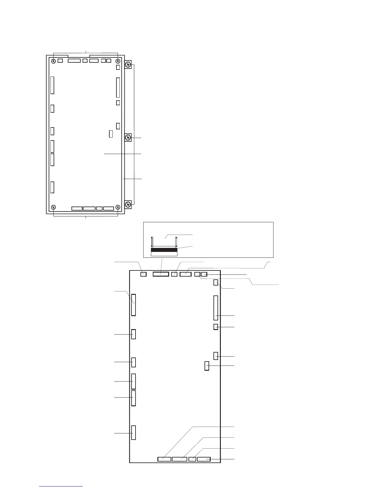
Replacing the Printed Circuit Board A
To remove:
1. Remove the face cover, bed cover and front cover (refer
to pages 1, 3 and 4).
2. Disconnect all the connectors from the printed circuit
board A.
3. Remove the 3 setscrews (A) and remove the printed
circuit board A with the case.
4. Remove the 4 setscrews (B) and remove the printed
circuit board A from the case.
To attach:
1. Follow the above procedure in reverse.
NOTE:
Refer to the following diagram when connecting the
connectors.
Setscrews (B)
Setscrews (A)
Setscrew (B)
Printed circuit
board A
Case
Disconnecting LCD Module Flexible PCB
Flexible PCB
Lift up the clamp to unlock.
Close the clamp to lock.
Touch panel (Black)
Program (slave)(Black)
Printed circuit
board L1(Black)
Printed circuit board L2 (White)
Printed circuit
board L3(Red)
Printed circuit board F(Black)
Presser foot lifter sensor(Black)
Thread detection sensor (White)
Switching power supply (White)
Thread cutter motor (White)
Switching power supply (White)
Y-motor
Bobbin thread
detecting sensor (Green)
Bobbin thread winding
Program (master)
Phase sensor
USB
X-motor
Thread tension motor
DC motor
Printed circuit board A connection