


H
Holly MerrittJul 30, 2025
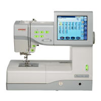
What to do if the bobbin thread breaks on my Janome MC 11000 Sewing Machine?
- DDonald HaydenJul 31, 2025
If the bobbin thread is breaking in your Janome Sewing Machine, there are several potential causes. First, ensure the bobbin thread is correctly threaded in the bobbin holder. Second, check for lint accumulation in the bobbin holder. Finally, inspect the bobbin for damage; if damaged, replace the bobbin.