15
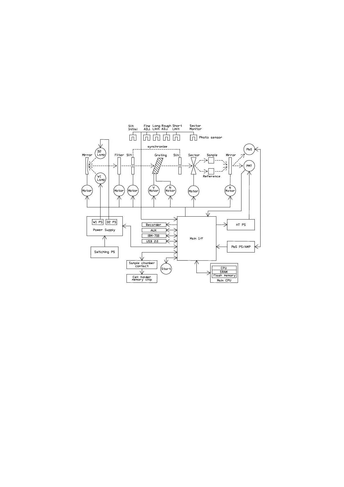
(2) Electrical System
Figure 3.6 shows a schematic diagram of the electrical system used in the V-650, V-660 and V-
670 spectrophotometers. The light incident upon the photomultiplier tube or PbS photoconductive
cell is converted into an electrical signal and, after being subjected synchronous rectification, it is
converted into a digital signal. The signal processed by the computer is displayed on the monitor
as digital data or a spectrum.
Actions such as light source exchange, wavelength drive, slit drive, filter drive, etc. are controlled
by the computer.
Figure 3.6 V-650/660/670 electrical system diagram