Transmission
Electrical Connections
Section F Section F
9808/3280
Issue 1
33-10
33-10
Powershift Gearbox - 6 Speed (cont’d)
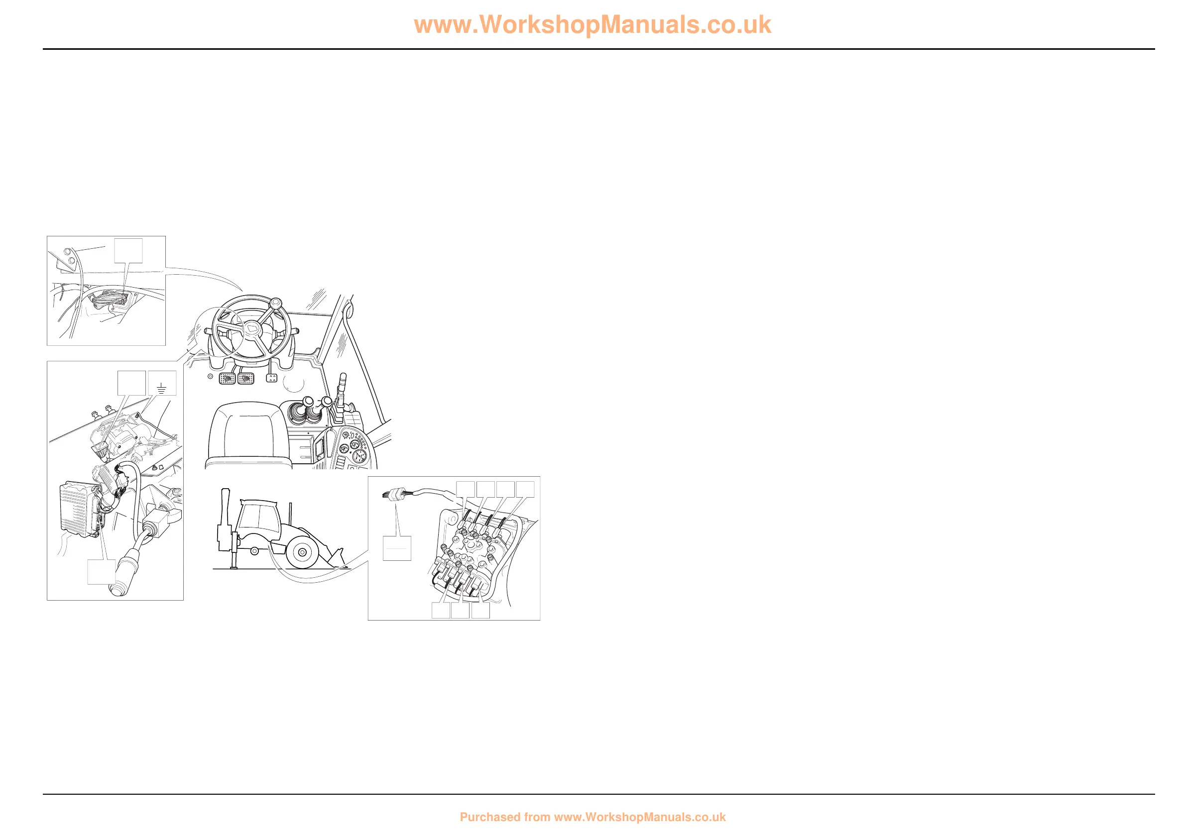
Electrical Connections - Wires and Connectors
Gearbox Solenoid Actuation
For input controls see previous page.
Component Key (solenoid activation):
The following key identifies the component connectors on
the diagrams opposite. Note that the wires coloured green
show the electrical ‘feed to earth’ for the gearbox mounted
solenoids and gearbox ECU.
h1 Harness - 721/10937 Front console
h2 Harness - 721/10971 Link
h5 Harness - 721/10941 Gearbox
Note: For harness drawings see Section C.
Connectors (h1)
GC E.C.U. connector B
FA h1 î h2
FB1 Earth point
Connectors (h2)
LA h1 î h2
LC h2 î h5
Connectors (h5)
C10 h5 î h2
C20 Gearbox solenoid U (labelled E)
C30 Gearbox solenoid T (labelled F)
C40 Gearbox solenoid Y (labelled G)
C50 Gearbox solenoid Z (labelled H)
C60 Gearbox solenoid W (labelled I)
C70 Gearbox solenoid V (labelled J)
C90 Gearbox solenoid X (labelled 6)
Splices (h1)
SA
Splices (h2)
SC
Splices (h5)
SA
Earth Points
Faults may be caused by poor earth connections. Although
earth connections are shown opposite, it must be
remembered that the cab assembly is earthed via further
earth strap and cable connections. For details of these
connections see Section C, Machine Earth Connections.