14 -1 5
Section E Hydraulics
9803/6410
Section E
14 - 15
Issue 1
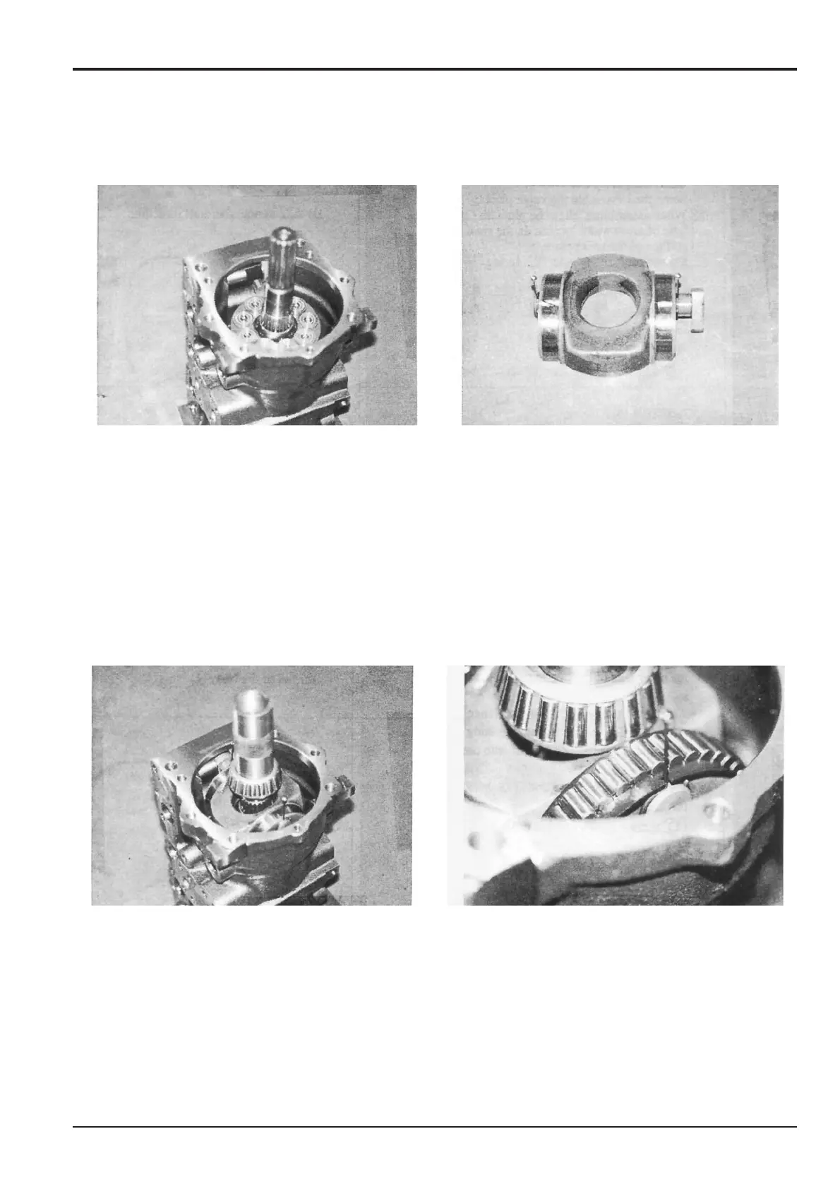
Hydraulic Pump/Regulator
7 Using suitable blocks to allow the shaft to clear the
work surface, position the pump housing on the bench,
front end uppermost.
8aFit the two guide assemblies 21 and slide metal 22
to swash plate 7.
Note: The hole in slide metal 22 is not central. Install with
the hole furthest from the pistons.
b Assemble swash plate 7 into the pump housing.
Note: Position regulator piston 23 with the groove for slide
metal 22 in the centre and locate the two during assembly.
Assembly (cont’d)
9 Using a suitable tool (see Service Tools, Section 1) and
a press, fit bearing 3 onto shaft 5.
Note: This job can be carried out by drifting the bearing into
place, taking care not to scratch or damage the bearing, the
shaft or any other parts.
10 Fit bearing cage/rollers 14 on swash plate 7. Set guide
assembly 21 in the cut-out of the bearing cage,
standing upright.