14 - 16
Section E Hydraulics
9803/6410
Section E
14 - 16
Issue 1
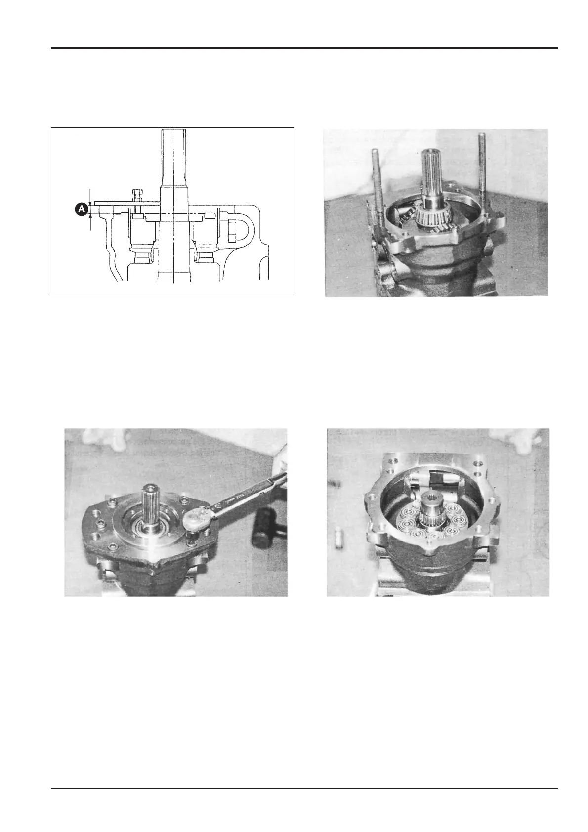
Hydraulic Pump/Regulator
11 Using a swash plate levelling jig (see Service Tools,
Section 1), adjust swash plate 7 so that it is parallel
with the outer face of pump housing 1, by ensuring the
same height A on the left and the right
12 Install two guide rods (see Special Tools, Section 1)
into opposite threaded holes in the pump housing
flange.
Assembly (cont’d)
13 a Insert two pins 64 into flange 2, then fit the outer
race of bearing 13 into the flange.
b Fit ‘O’-ring 78 into the flange.
c Insert pin 62 into pump housing 1 and then
assemble flange 2 onto the housing along the guide
rods fitted at step 12.
d Install four socket head bolts 73 into the vacant
mounting holes. Remove the two guide rods and
insert the remaining two bolts 73. Tighten the bolts
evenly to a torque of 129 Nm (95 lbf ft, 13.1 kgf m).
14 Lay the pump housing on its side and repeat steps 1, 2
and 3 at the rear end of the housing. Fit the cylinder
block assembly on the spline of shaft 5.
Using suitable blocks to allow the shaft to clear the
work surface, position the pump housing on the bench,
rear end uppermost.
JS00110