14 - 18
Section E Hydraulics
9803/6410
Section E
14 - 18
Issue 1
Hydraulic Pump/Regulator
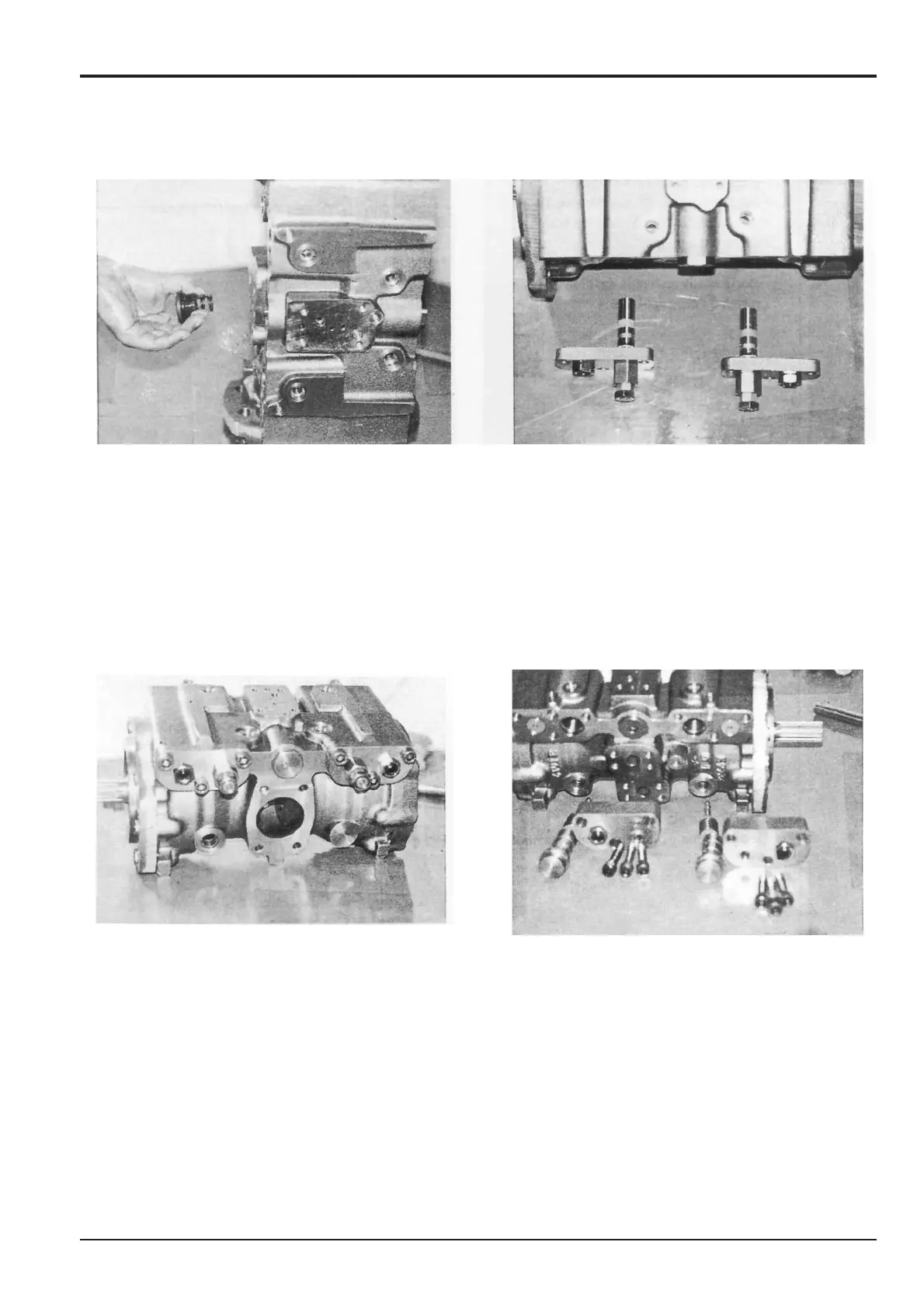
18 Insert spring 36. Fit ‘O’-ring 84 onto plug 35 and then
screw the plug into the pump housing and tighten to a
torque of 157 Nm (116 lbf ft, 16 kgf m).
19 Fit ‘O’-ring 88 and back-up ring 98 onto sleeve 39,
taking care not to damage the wire mesh filter around
the outside. Install the sleeve into cover ‘R’ 30 and
temporarily tighten with nut 48.
In order, install spring seat 46, spring 47 and plug 45
with ‘O’-ring 92 fitted into sleeve 39 and fit locking nut
49.
Install set screw 26 complete with locking nut 28 into
cover ‘R’ 30.
Assembly (cont’d)
20 Install assembled cover ‘R’ 30 into the pump housing,
first aligning the slot in bridging piece 29 (by means of a
piece of wire from the opposite side) to accommodate
sleeve 39. Install the three socket head bolts 73 and
tighten to a torque of 129 Nm (95 lbf ft, 13.1 kgf m).
Note: Having been dismantled it will be necessary to make
adjustments on the bench to the variable components
secured by locking nuts 28, 48 and 49. On completion of the
adjustments torque tighten as follows:
28 73 Nm (54 lbf ft, 7.5 kgf m)
48 182 Nm (134 lbf ft, 18.5 kgf m)
49 45 Nm (33 lbf ft, 4.5 kgf m)
Repeat steps 19 and 20 for cover ‘F’ 30.
21 Install spring seat 41, springs 43 and 44 and spring
seat 42 onto spool 40.
Note: The larger diameter side of spring seat 42 should be
against springs 43 and 44.