14 - 19
Section E Hydraulics
9803/6410
Section E
14 - 19
Issue 1
JS01840
Hydraulic Pump/Regulator
22 Fit ‘O’-ring 83 onto sleeve 37. Insert the three pistons
38 and piston 54 into the sleeve.
Fit set screw 27 and locking nut 28 into front cover 52.
Install spool 40 assembly, followed by sleeve 37
assembly into the pump housing, making sure spool 40
moves freely and that pistons 38 (3 off) and 54 do not
fall out. Secure cover 52 with the three socket head
bolts 72 tightened to a torque of 129 Nm (95 lbf ft, 13.1
kgf m).
Repeat steps 22 and 23 for rear cover 53.
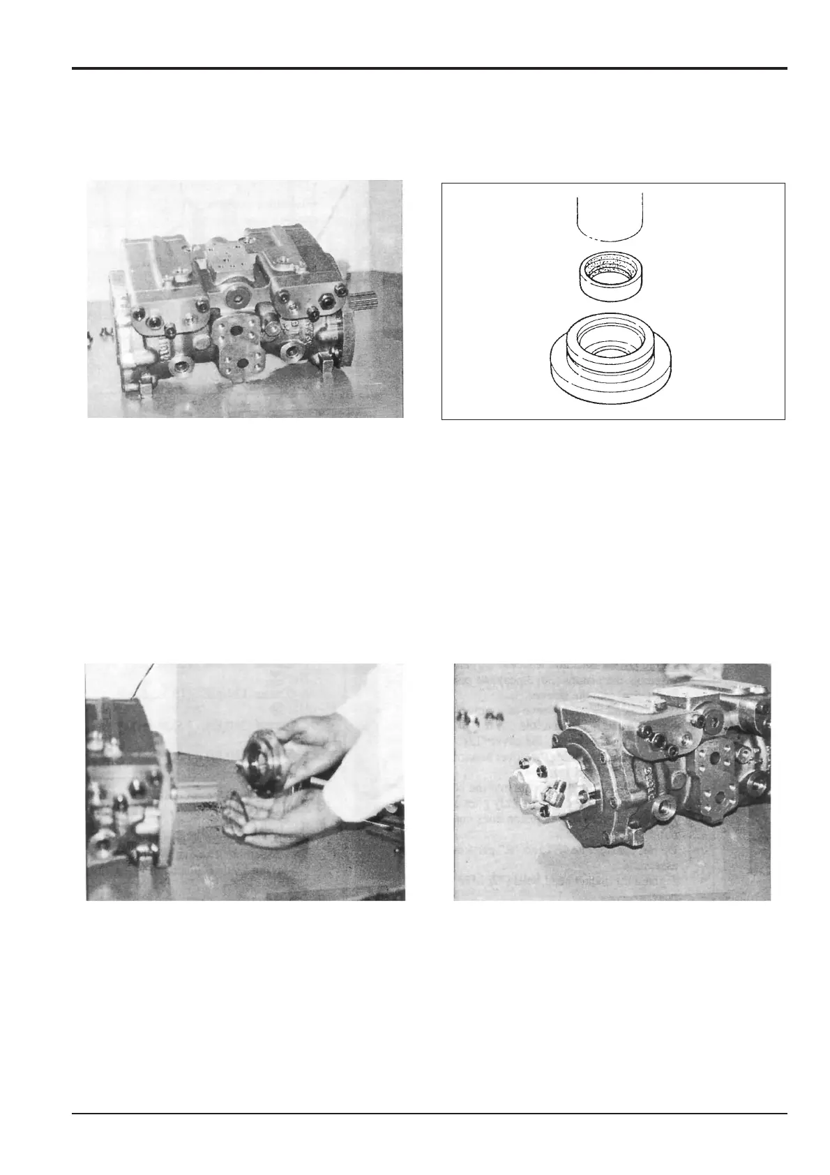
23 Using a suitable tool (see Service Tools, Section 1) and
a press, fit oil seal 15 squarely into oil seal case 16 with
the open side of the seal facing flange 2. Fit ‘O’-ring 79
onto the oil seal case.
Assembly (cont’d)
24 Fit shims 17 and 18 (if used) and oil seal case 16
assembly onto flange 2. Install the four socket head
bolts 75 and torque tighten to 33 Nm (24 lbf ft, 3.3 kgf
m).
Note: Shims 17 and 18 provide clearance adjustment, if
required. Always re-fit the shims removed during
dismantling.
25 Fit ‘O’-ring 80 into rear cover 3. Install gear pump 57
and secure with washer 109 and the two bolts 77
tightened to a torque of 45 Nm (33 lbf ft, 4.5 kgf m).