14 - 20
Section E Hydraulics
9803/6410
Section E
14 - 20
Issue 2*
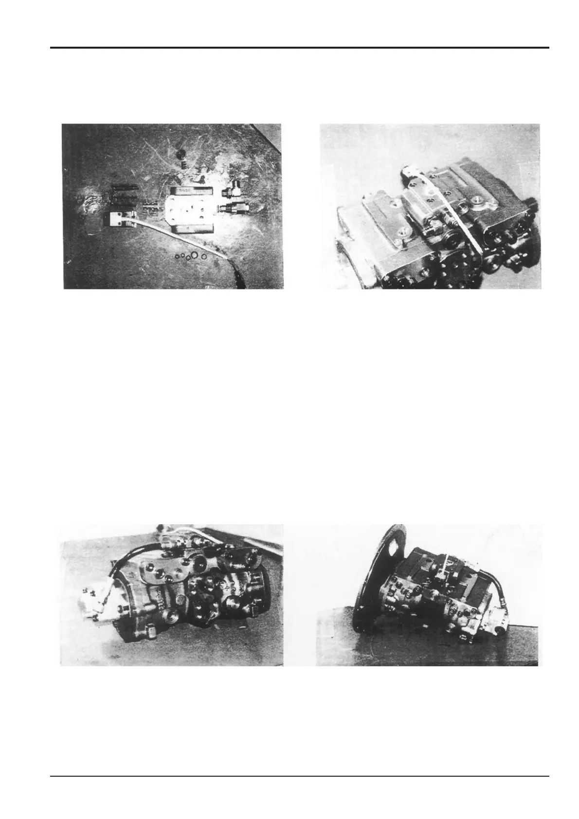
Hydraulic Pump/Regulator
26 Assemble sub-block 50 as follows:
a Fit relief valve 56.
b Fit adjustable elbow 60, making sure the elbow
faces away from the relief valve.
c Insert disc filter 51 followed by spring 104 and plug
107 complete with ‘O’-ring 108.
d Insert spool 103 into sleeve 102 with the drilled end
of the spool corresponding to the stepped end of
the sleeve. Insert the assembly, stepped end of
sleeve first, into the block. Mount solenoid 58.
e Into the mounting face of the block, insert ‘O’-rings
89, 91, 93 (2 off), and 111, the second disc filter 51
and orifice 110.
Note: Check that the orifice and its mounting position are
not clogged.
27 Fit sub-block 50 assembly onto the pump housing and
secure with the four socket head bolts 74, tightened to
a torque of 33 Nm (24 lbf ft, 3.3 kgf m).
Tighten the following parts of the sub-block assembly
to the specified torque:
Relief valve 56 - 83 Nm (61 lbf ft, 8.5 kgf m)
Plug 107 - 52 Nm (38 lbf ft, 5.2 kgf m)
Solenoid 58 retaining screws (x 4) - 4.2 Nm (3.1 lbf ft,
0.43 kgf m)
Assembly (cont’d)
28 Connect hose 59 to the two adjustable elbows 60 and
tighten to a torque of 52 Nm (38 lbf ft, 5.2 kgf m).
29 Tighten plugs 65 and 66 to a torque of 71 Nm (52 lbf ft,
7.2 kgf m) and plug 67 to 30 Nm (22 lbf ft, 3.0 kgf m).
Fit mounting flange 61 to flange 2 and secure with the
four socket head bolts 71 tightened to a torque of
275 Nm (203 lbf ft, 28 kgf m).
*