Dismantling (cont’d)
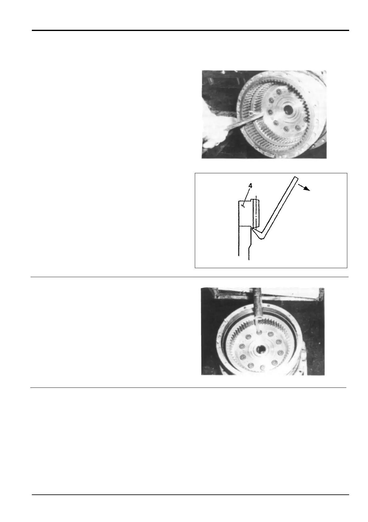
4 Make matching marks on ring gear 4 and hub 1 to aid
assembly.
Using a bar, withdraw ring gear 4 and remove the
adhesive from the engagement surfaces of the ring gear
and hub.
Remove the ten parallel pins 27 from hub 1.
5 Remove the ten socket bolts 35.
Note: There is adhesive on the threads of the socket bolts
35. So a loosening torque higher than the tightening torque
will be required. Take extra care that seizures do not occur.
Match mark the coupling gear 8 and spindle 2 to aid
assembly. Remove the coupling gear.
6 Install four eye bolts (M12) in the threaded holes on the
flange of hub 1. Use suitable lifting gear to separate hub
1 from spindle 2.
The two bearings 24, seal ring 23, ‘O’-ring 40, coupling
gear 8, ring gear 5, ring 15 and distance piece 12 will
also be released at this time.
10 - 2
Section F Transmission
9803/6410
Section F
10 - 2
Issue 1
Reduction Gear - JS160
JS00550