10 - 1
Section F Transmission
9803/6410
Section F
10 - 1
Issue 1
Reduction Gear - JS160
Dismantling
Refer to the following pages:
7 - 6 and 7 - 8 (illustrations)
7 - 9 to 7 - 10 (component list)
In the following procedures, the part numbers in bold type
(e.g. 13) correspond with the numbers on the illustrations.
Before attempting to dismantle the reduction gear, drain all
oil, blank all inlet and outlet ports and wash the outer
surfaces with a suitable solvent to remove all dirt and dust.
Dry using compressed air.
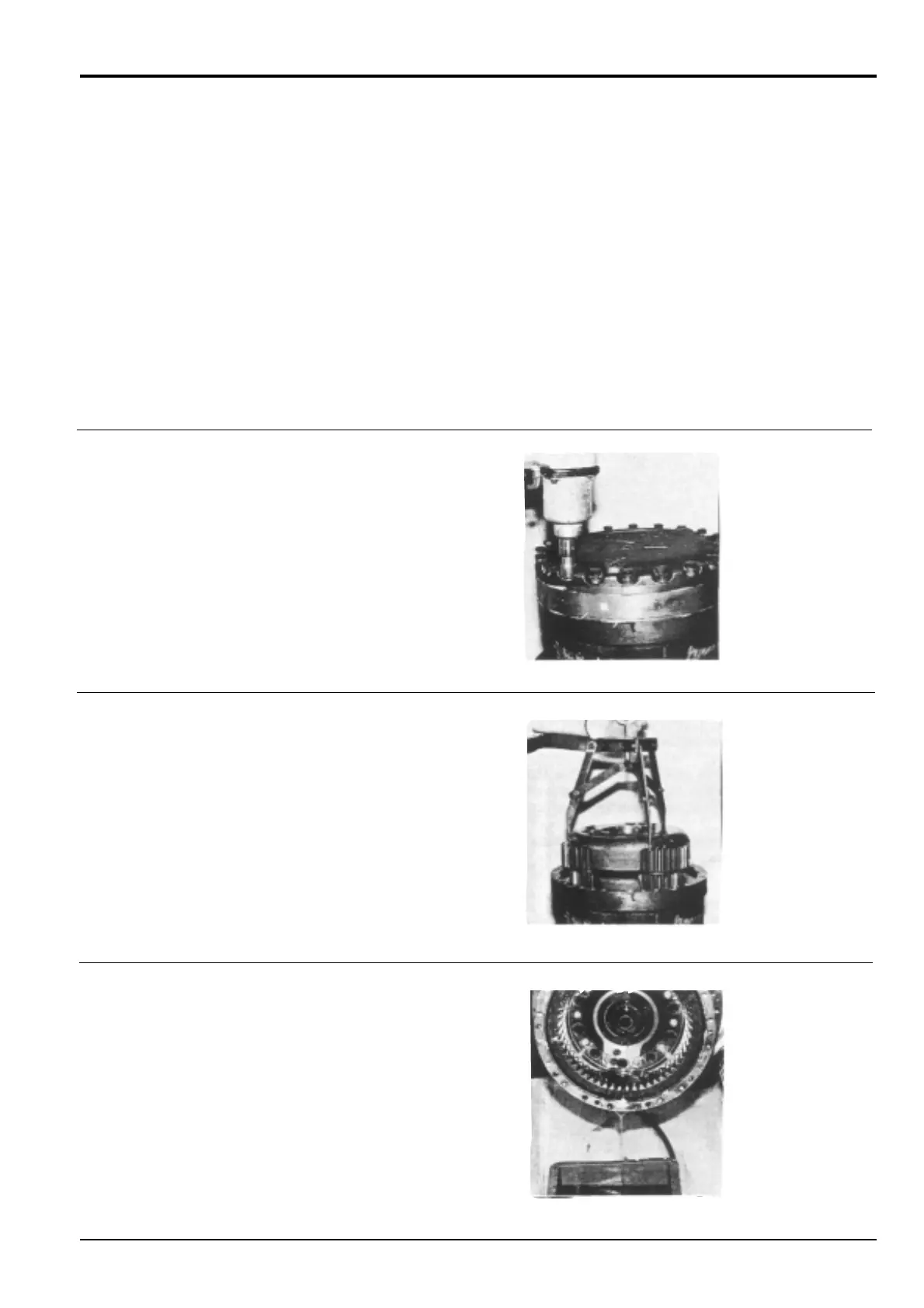
1 Place the traction motor/reduction gear assembly on
the bench with cover 13 uppermost.
Remove the three plugs 30 and the twenty bolts
32/super lock washers 33.
2 Insert eye bolts in the cover holes vacated by plugs 30.
Use suitable lifting gear to remove cover 13.
Remove outer thrust bearing 20. Using a suspension
fitting 1 (see Service Tools, Section 1) lift out the
carrier 3 assembly.
Remove steel ball 36, sun gear 7, coupling 19 and
inner thrust bearing 20.
3 Drain the gear oil from the reduction gear housing.
Make different alignment marks across each sub assembly
joint face as an aid to assembly.
During dismantling, record the number and dimensions of
shims. Take care to reassemble in the same manner.