Adjustments (cont’d)
Determining the Thickness of Snap Ring 20
This procedure must be carried out if any of the following
components have been renewed: spindle 2, flange 3, gear
assembly (items 4, 5, 9, 22 and 23). The procedure, referring
to only one crankshaft 9, should be repeated for all three.
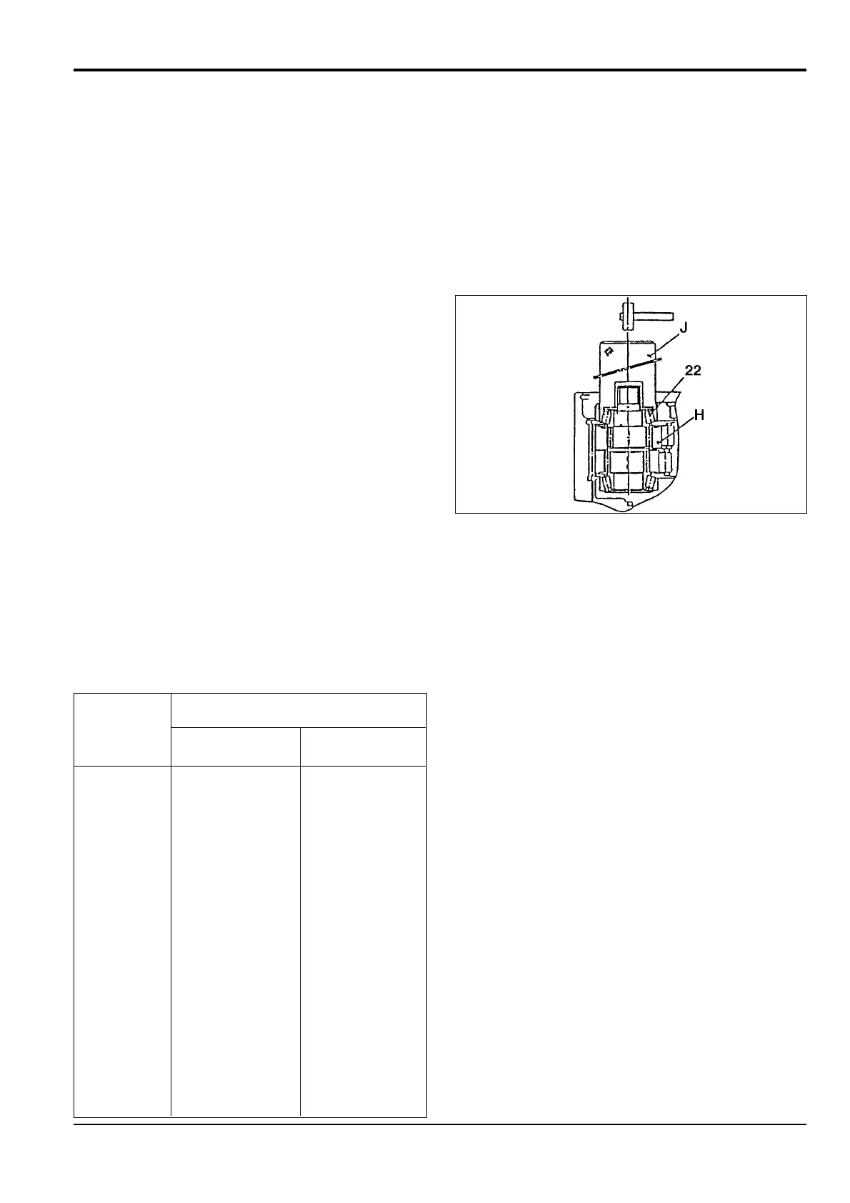
1 Lightly tap the outer ring of bearing 22 installed on
crankshaft 9 of gear assembly H, using press jig J and
a hammer to make sure the gear is fully seated in
spindle 2.
2 Install the thinnest snap ring 20 into the snap ring
groove in flange 3.
3 Lightly tap the outer part of the snap ring with the press
jig and a hammer.
4 Use a feeler gauge between snap ring 20 and bearing
22 to measure the clearance.
5 The required snap ring thickness T = feeler gauge
thickness + thickness of snap ring installed ± 0.05 mm
(0.002 in). Select a suitable snap ring from the twelve
detailed below.
T
Snap ring 20
Identification
Min Max
A 2.20 mm (0.0866 in) 2.25 mm (0.0886 in)
B 2.25 mm (0.0886 in) 2.30 mm (0.0906 in)
C 2.30 mm (0.0906 in) 2.35 mm (0.0925 in)
D 2.35 mm (0.0925 in) 2.40 mm (0.0945 in)
E 2.40 mm (0.0945 in) 2.45 mm (0.0965 in)
F 2.45 mm (0.0965 in) 2.50 mm (0.0984 in)
G 2.50 mm (0.0984 in) 2.55 mm (0.100 in)
H 2.55 mm (0.100 in) 2.60 mm (0.102 in)
I 2.60 mm (0.102 in) 2.65 mm (0.104 in)
J 2.65 mm (0.104 in) 2.70 mm (0.106 in)
K 2.70 mm (0.106 in) 2.75 mm (0.108 in)
L 2.75 mm (0.108 in) 2.80 mm (0.110 in)
9 - 10
Section F Transmission
9803/6410
Section F
9 - 10
Issue 1
Reduction Gear - JS130
JS00530