7 - 34
CHAPTER 7 Diagnostics
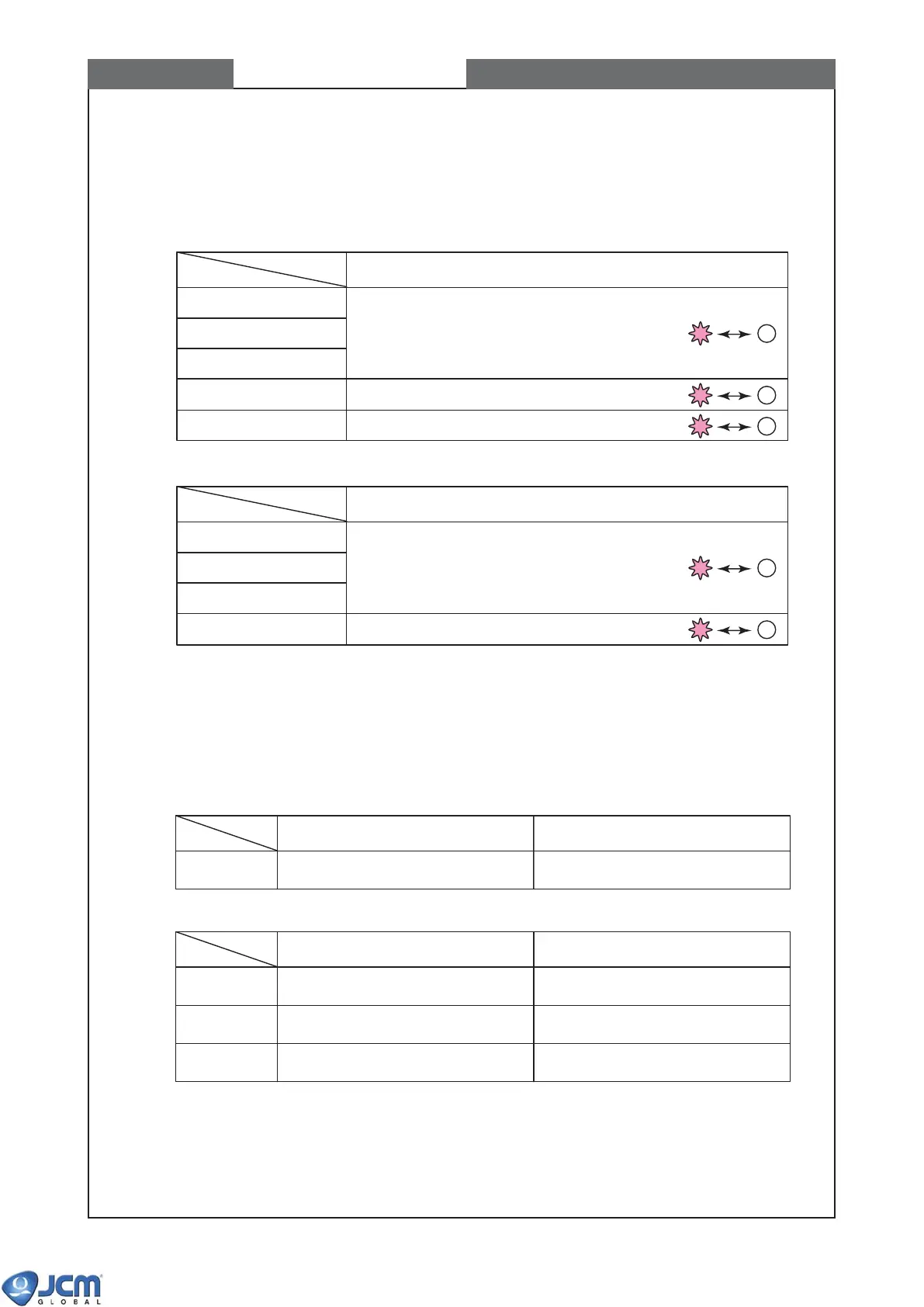
DIR
SICLK
SETLD
MDB TXD
Mode display LED1 to LED5
Repeat blinking by 200ms in sequence from
DIR=>SICLK=>SETLD=>DIR,SICLK,SETLD.
Repeat blinking by 200ms.
Repeat blinking by 200ms in sequence from LED1 to LED5.
VM-30 LED
CCT TXD
HII TXD
HII TALK
Mode display LED1 to LED5
Repeat blinking by 200ms in sequence from
CCT TXD=>HII TXD=>HII TALK.
Repeat blinking by 200ms in sequence from LED1 to LED5.
VM-30 LED
MDB RXD
LED1 turns "ON", when MDB RXD of VM-30
switched to "ON"
LED1 turns "OFF", when MDB RXD of VM-30
switched to "OFF"
"ON" condition of Mode Display LED "OFF" condition of Mode Display LED
LED1 turns "ON", when CCT RXD of VM-30
switched to "ON"
LED1 turns "OFF", when CCT RXD of VM-30
switched to "OFF"
LED2 turns "ON", when HII RXD of VM-30
switched to "ON"
LED2 turns "OFF", when HII RXD of VM-30
switched to "OFF"
LED3 turns "ON", when HII BUSY of VM-30
switched to "ON"
LED3 turns "OFF", when HII BUSY of VM-30
switched to "OFF"
CCT RXD
HII RXD
HII BUSY
"ON" condition of Mode Display LED "OFF" condition of Mode Display LED
5-4 Acceptor Interface Output Test
This is the test of output signal line from the acceptor to external I/F port and VM-30 mode display LED.
This is also the output test of red and green LEDs of acceptor.
(1) EBA-30/31 CPU board
(2) EBA-32/33 CPU board
5-5 Acceptor Interface Input Test
This is the test of acceptor's input signal line (external I/F port). The status of the input signal line is
shown on the VM-30 mode display LEDs.
(1) EBA-30/31 CPU board
(2) EBA-32/33 CPU board