7 - 30
CHAPTER 7 Diagnostics
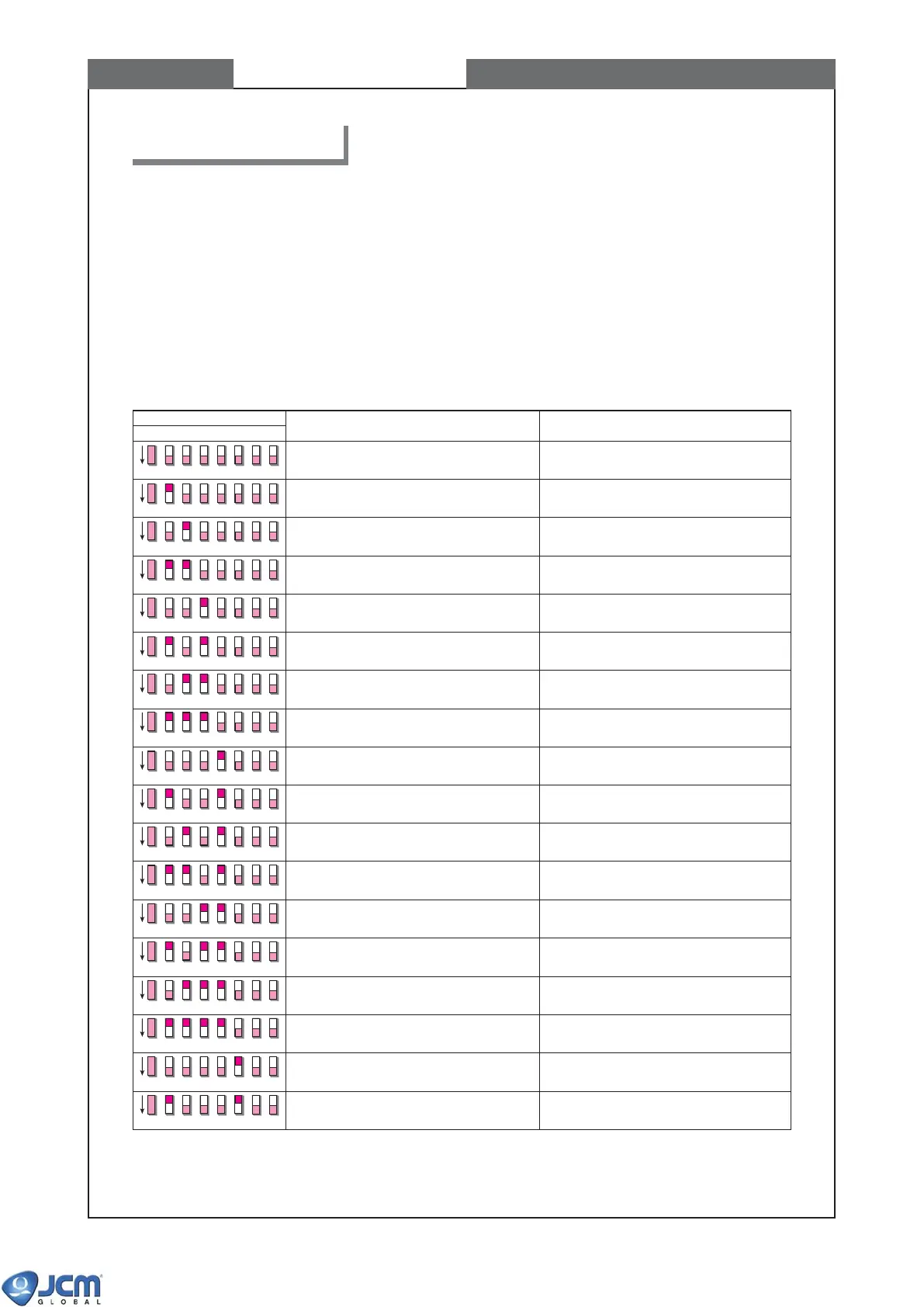
5. Diagnostics
1234
DIP SWITCH No.
ITEM DESCRIPTION
5678
Transport motor normal rotation test Transport motor speed test (normal rotation)
Transport motor reverse rotation test Transport motor speed test (reverse rotation)
Acceptor sensor ON/OFF test #1 Bill detection sensor test
Acceptor sensor ON/OFF test #2 Validation sensor test
Acceptor sensor ON/OFF test #3 Validation sensor test
Acceptor sensor ON/OFF test #4 Validation sensor test
Acceptor sensor ON/OFF test #5 Validation sensor test
Acceptor I/F test (OUT) External display output cirucit test
Acceptor I/F test (IN) External display input cirucit test
Acceptor bill acceptance test Bill acceptance and operation test
Acceptor+stacker bill acceptance test Bill acceptance and operation test
PB unit test PB unit and PB unit home sensor test
Centering mechanism test Centering mechanism and the home position
sensor test
Solenoid test Solenoid lever ON/OFF test
Stacker sensor test Stacker sensor test
Stacker stacking test Stacker pusher mechanism check and
stacker sensor test
Acceptor+stacker aging test Acceptor unit + stacker unit operation test
OFF
OFF
OFF
OFF
OFF
OFF
OFF
OFF
OFF
OFF
OFF
OFF
OFF
OFF
OFF
OFF
OFF
OFF
Acceptor aging test Acceptor unit operation test
Refer to Chapter 6, page 6-2 for appropriate cabling between EBA and VM-30.
To execute test modes, turn the power switch OFF, set the switch #1 of DIP switch 1 (see Chapter 1 page 1-4,
Component Names) to ON, and then turn the VM-30 power ON. The red and green LEDs of CPU turn on,
indicating the acceptor is in stand-by status.
Each test mode is selected by the assignment of DIP switches #2 to #8, and is executed by turning DIP switch #1
OFF. Turn DIP switch #1 ON to exit the test mode (i.e. return to the stand-by status of the test mode).
5-1 List of the DIP switch settings and the test mode items