2 - 14
CHAPTER 2 Operations and Maintenance
The DIP switches are to specify the types of acceptable denominations and operation mode of the bill
acceptor. DIP Switch 1 is located on the right side of CPU board, and Dip Switch 2 is located under ROM
cover. (See Chapter 1. 4 Component Names)
6-1 Settings of Dip Switch 1
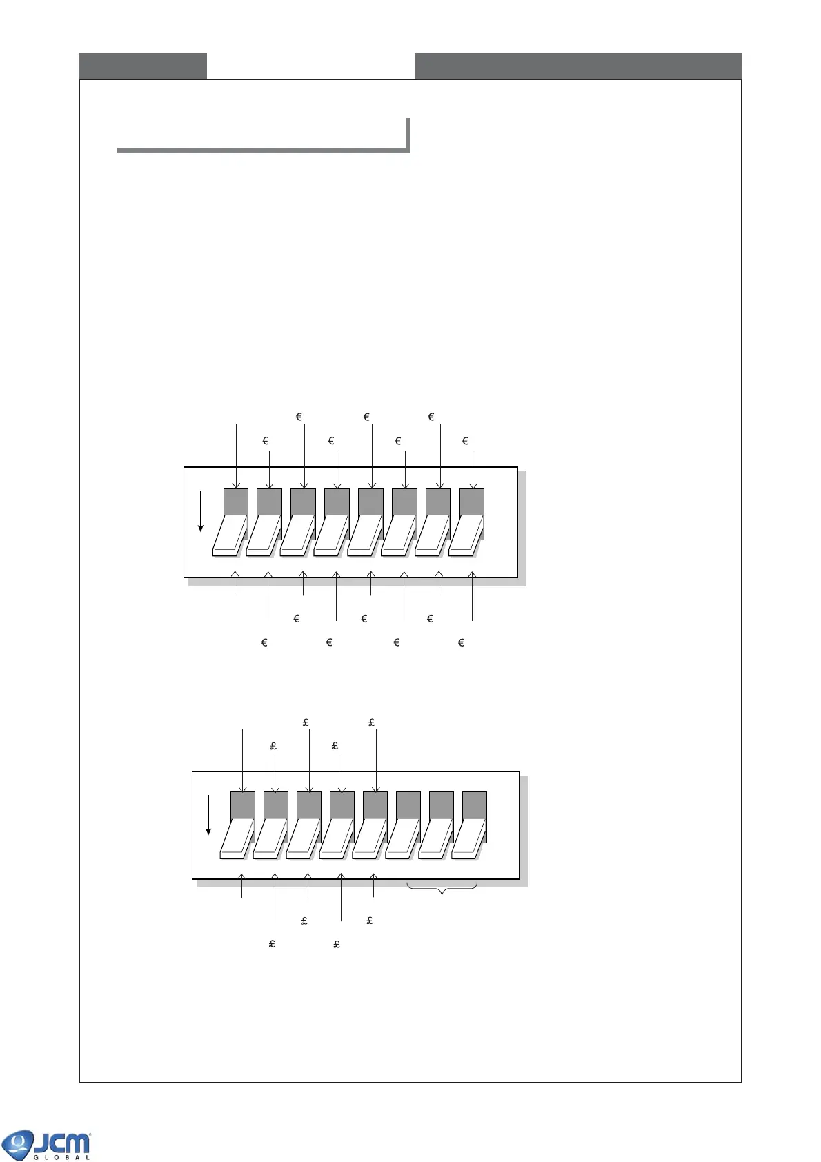
The DIP Switch 1 specifies the denominations to be accepted by the bill acceptor
Refer to the software specifications for the DIP switch settings.
<Example 1> EBA-30/31/34/35-SD3 (EUR5) and EBA-30/31/34/35 (EUR5)
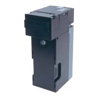
<Example 2> EBA-32/33-SD3 (GBR) and EBA-32/33 (GBR)
(Remarks) In both examples, Switch #1 of the DIP Switch 1 is the selector of normal operation and test
mode.
For normal operation, make sure to set Switch #1 to OFF before turning on the power.
If Switch #1 is ON at the time of power-on, the unit operates in test mode.
6. Description of DIP switches
OFF
12345678
(Test Mode)
Inhibit
5
Inhibit
10
Inhibit
20
Inhibit
50
Inhibit
100
Inhibit
200
Inhibit
500
Set to OFF
Accept
5
Accept
10
Accept
20
Accept
50
Accept
100
Accept
200
Accept
500
OFF
12345678
Set to OFF
(Test Mode)
Accept
5
Inhibit
5
Accept
10
Inhibit
10
Accept
20
Inhibit
20
Accept
50
Set to OFF
[RESERVED]
Inhibit
50