2 - 10
CHAPTER 2 Operations and Maintenance
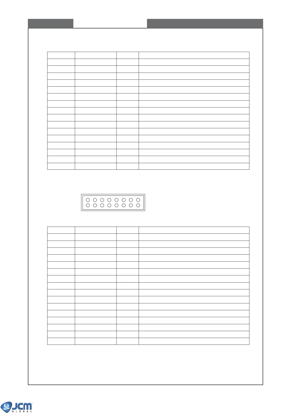
4-2-3 The pin assignment of ID-0F3 HII serial interface
Description of signal
Power supply input 12V
GND
Power supply input 12V
GND
NC (Do not use this pin for ID-0F3.)
NC (Do not use this pin for ID-0F3.)
NC (Do not use this pin for ID-0F3.)
NC (Do not use this pin for ID-0F3.)
NC (Do not use this pin for ID-0F3.)
NC (Do not use this pin for ID-0F3.)
NC (Do not use this pin for ID-0F3.)
HII Data Return
HII/Data: HII data line
HII Busy return
HII/Busy: BUSY line
HII/Reset: Reset line
Pin No.
1
2
3
4
5
6
7
8
9
10
11
12
13
14
15
16
Signal name
+12V
GND
+12V
GND
(TXD)
(SG)
(RXD)
(SG)
(+5V)
(GND)
ccTalk TXD/RXD
SG
(HII DATA)
SG
(HII BUSY)
Reset
I/O
In
In
Out
In
Out
In/Out
In/Out
In/Out
In
16 2
15 1
CN2
4-3 Interface connector CN2 on the EBA-34/35 CPU board
4-3-1 The pin assignment of ID-003 JCM bidirectional serial interface
Description of signal
Power supply input +12V or +24V
GND
Power supply input +12V or +24V
GND
Output signal line from acceptor to controller
Signal ground
Input signal line from controller to acceptor
Signal ground
NC (Do not use this pin for ID-003.)
NC (Do not use this pin for ID-003.)
NC (Do not use this pin for ID-003.)
NC (Do not use this pin for ID-003.)
NC (Do not use this pin for ID-003.)
NC (Do not use this pin for ID-003.)
NC (Do not use this pin for ID-003.)
NC (Do not use this pin for ID-003.)
Pin No.
1
2
3
4
5
6
7
8
9
10
11
12
13
14
15
16
Signal name
+12V/+24V
GND
+12V/+24V
GND
TXD
SG
RXD
SG
(MTXD)
(MRXD)
(MCOM)
(DIR)
(SICLK)
(SG)
(SETLD)
(SG)
I/O
In
In
Out
In