P/N 960-100189RA_Rev. A {EDP #148850} © 2009, Japan CashMachine Co., Limited
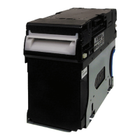
VEGA™ Series
BankNote Validator
List of Figures
Page
LOF
Figure 1-1 VEGA Unit Assembly ............................................................................. 1-1
Figure 1-2 Precautionary Symbols .......................................................................... 1-2
Figure 1-3 Unacceptable Banknotes ....................................................................... 1-3
Figure 1-4 VEGA Component Names ..................................................................... 1-4
Figure 1-5 VEGA System Configuration with Host destination example ................. 1-5
Figure 1-6 VEGA Banknote Validator Unit Outside Dimensions
(Type SH - Standard Cash Box) ............................................................ 1-8
Figure 1-7 VEGA Mounting Space Clearance Dimensions
(Type SH - Standard Cash Box) ............................................................ 1-8
Figure 1-8 VEGA Banknote Validator Unit Outside Dimensions
(Type SH - Large Cash Box).................................................................. 1-9
Figure 1-9 VEGA Banknote Validator Unit Outside Dimensions
(Type SH - Large Cash Box).................................................................. 1-9
Figure 1-10 VEGA Banknote Validator Unit Outside Dimensions
(Type SD/SU - Standard Cash Box) ................................................... 1-10
Figure 1-11 VEGA Banknote Validator Unit Outside Dimensions
(Type SD/SU - Large Cash Box).......................................................... 1-10
Figure 1-12 VEGA Banknote Validator Unit Outside Dimensions
(Type SD/SU Rear Access) ................................................................. 1-11
Figure 1-13 VEGA Cash Box Outside Dimensions (Standard Cash Box)............... 1-11
Figure 1-14 VEGA Cash Box Outside Dimensions (Large Cash Box) .................... 1-12
Figure 1-15 VEGA Bezel Outside Dimensions (Type SH) ...................................... 1-12
Figure 1-16 VEGA Bezel Outside Dimensions (Type N)......................................... 1-13
Figure 1-17 VEGA Bezel Outside Dimensions (Type D)......................................... 1-13
Figure 2-1 M4 Nut & DIP Switch Locations ............................................................. 2-1
Figure 2-2 Cable Interconnection ............................................................................ 2-1
Figure 2-3 Bezel Attachment ................................................................................... 2-2
Figure 2-4 M4 Screw & Nut Locations..................................................................... 2-2
Figure 2-5 Cash Box & Guide Cover Location ........................................................ 2-2
Figure 2-6 DIP Switch DS1 (Gradient Color
Setting) ................................................ 2-3
Figure 2-7 DIP Switch DS1 (Blue C
olor Setting) ..................................................... 2-3
Figure 2-8 DIP Switch DS1 (Green Color Setting) .................................................. 2-3
Figure 2-9 DIP Switch DS1 (cc-Talk Initialize)......................................................... 2-3
Figure 2-10 Retrieving Banknotes............................................................................. 2-5
Figure 2-11 Opening the Upper Validation Section................................................... 2-5
Figure 2-12 Retrieving Cash Box Banknote Jam ...................................................... 2-5
Figure 2-13 VEGA Sensor Cleaning Locations ......................................................... 2-6
Figure 2-14 VEGA Photo Coupler Circuit Interface Schematic Diagram .................. 2-7
Figure 2-15 VEGA RS-232C Circuit Interface Schematic Diagram........................... 2-7
Figure 2-16 VEGA ccTalk Circuit Interface Schematic Diagram ............................... 2-7

 Loading...