14
8.7 Chip brush
The wire chip brush must be properly adjusted and
maintained in working condition; otherwise damage
to blade can occur. Adjust brush so that its bristles
overlap blade.
Replace brush if it becomes worn or damaged.
8.8 Blade tension
1. Disconnect machine from power source.
2. Open rear guard by removing 2 knobs (see
Figure 8-10). Observe position of blade on
wheel. If blade is not adjacent to wheel flange,
first adjust blade tracking according to sect. 8.9
Blade tracking.
3. If blade is properly adjacent to wheel flange,
slide blade guide assemblies as far apart as
possible, and tighten in position with knobs (N,
Figure 8-7).
4. Push on blade to test tension. Finger pressure
should cause approximately 0.004" deflection.
Turn blade tension handle (P, Figure 8-7) until
proper tension is achieved. For more precise
measurement use blade tension gauge (not
provided).
5. Return blade guides to operating position.
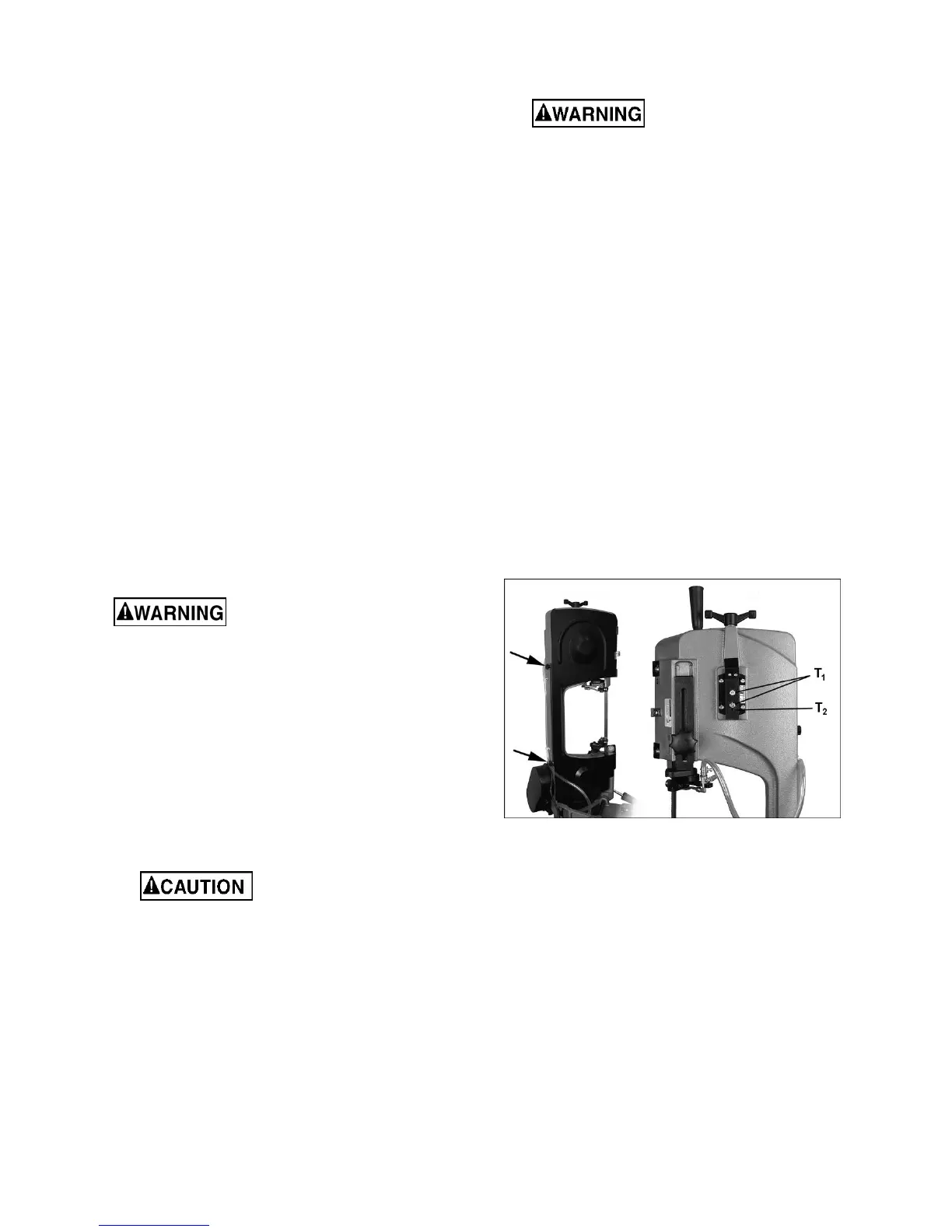
8.9 Blade tracking
Blade tracking adjustment
requires running saw with rear guard open. This
adjustment must be completed by qualified
persons only. Failure to comply may cause
serious injury.
Blade tracking has been set by the manufacturer
and should not need immediate adjustment. If blade
tracking should ever require adjustment:
1. Confirm that blade tension is properly set.
2. Set saw to slowest speed.
3. Raise bow to vertical position.
4. Open blade cover.
While performing the
following steps, keep blade from rubbing
excessively on wheel shoulder. Excessive
rubbing will damage wheel and/or blade.
5. Run saw and observe blade. Blade should run
next to but not tightly against wheel shoulder.
6. If blade is not tracking properly, loosen bolts (T
1
,
Figure 8-10) with 12mm wrench.
7. Turn set screw (T
2
) with 4mm hex key, while
observing blade tracking on wheel. Turn set
screw clockwise to track closer to wheel
shoulder. Turn set screw counterclockwise to
track away from wheel shoulder. NOTE: This
adjustment is sensitive; start with 1/4-turns on
set screw and allow blade to respond to
changes.
Keep fingers clear of blade
and wheel to avoid injury.
8. Test the setting by placing a six-inch length of
paper between blade and wheel. The paper
should not be cut as it passes between wheel
shoulder and blade.
9. Turn set screw (T
2
) a small amount. Repeat
insertion of paper between the shoulder and the
blade until paper is cut into two pieces.
NOTE: You may have to repeat the check with
the paper several times before blade and
shoulder cut the paper into two pieces. Do not
hurry the adjustment. Patience and accuracy
here will pay off with better, more accurate,
quieter cutting and longer machine and blade
life.
10. When paper is cut, back off set screw slightly.
This assures that blade is not touching wheel
shoulder.
IMPORTANT: If blade is allowed to run against
wheel shoulder, it will wear off the shoulder.
11. Once tracking is set, tighten bolts (T
1
).
Figure 8-10: blade tracking adjustment
8.10 Test cut to verify adjustment
Test cuts can be used to determine whether or not
you have adjusted the blade accurately. Use 2-inch
round bar stock to perform these test cuts, as
follows:
1. With bar stock securely clamped in vise, make
a cut through the bar stock. (See Figure 8-11.)
2. Mark the top of bar stock.
3. Move the bar stock about 1/4-inch past the
blade so that you can begin a second cut.
4. Rotate the bar stock 180 degrees so mark you
made is now at bottom of cut.
5. Make a cut through the bar stock.
 Loading...