8
6.0 Setup and assembly
Read and understand all
instructions before attempting assembly. Band
Saw must be disconnected from power during
all assembly procedures. Failure to comply may
cause serious injury.
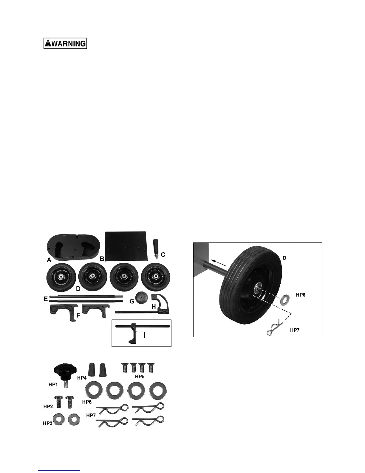
6.1 Shipping contents
See Figures 6-1, 6-2.
1 Band saw (not shown)
1 Pulley cover – A
1 Table Plate – B
1 Handle with washer and nut – C
4 Wheels – D
2 Axles – E
2 Supports (1 long, 1 short) – F (712D only)
1 Filter assembly – G
1 Work stop assembly – H (712D only)
1 Work stop assembly – I (712 only)
1 Hardware package (p/n HVBS712-HP):
1 Lock screw – HP1
2 Hex cap bolts 1/4 x 1/2 – HP2
2 Flat washers 1/4 – HP3
2 Wire nuts – HP4
4 Flat head screws 1/4 x 3/8 – HP5
4 Flat washers 5/8 – HP6
4 Cotter pins – HP7
Figure 6-1: shipping contents
Figure 6-2: hardware package HVBS712-HP
6.2 Tools required for assembly
Wrenches, 10mm and 19mm
#2 cross point screwdriver
Pliers
6.3 Unpacking and cleanup
1. Inspect all contents for shipping damage.
Compare contents of shipping carton with
contents list in this manual. Report any damage
or part shortages to your distributor.
2. Do not discard packing material until saw is
assembled and running properly.
3. Remove rust protectant from exposed surfaces,
such as bed, vise assembly, etc., with a clean
rag and a cleaner/degreaser. Apply a light coat
of oil on these surfaces to inhibit rust.
6.4 Assembly
Note: Most figures in this manual show 712D Deluxe
model. Procedures for 712 basic model will be
identical, except where noted.
1. Remove braces holding saw stand to pallet, and
carefully raise saw from pallet, using properly
rated lifting equipment (hoist or forklift) with
straps placed beneath cast iron portion of saw.
2. Slide axles through holes in stand, and install
four wheels with flat washers and cotter pins
(Figure 6-3). Bend ends of cotter pins to secure
wheel, then carefully lower saw to floor.
Figure 6-3: installing wheels
3. Remove shipping bracket (Figure 6-4). Then
reinstall bottom hex nut beneath plate. Retain
shipping bracket in case machine must be
transported in future.
 Loading...