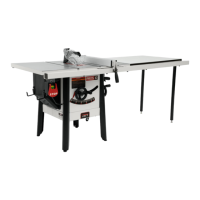
9
Figure 6-4: shipping bracket removal
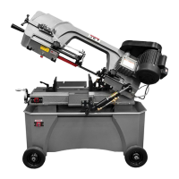
4. Install handle with flat washers and nut (C,
Figure 6-5), using 19mm wrench. To install,
raise bow to vertical position and open guard.
CAUTION: Spring-tensioned stop bracket (see
Figure 7-1) must be rotated out of the way
before raising bow.
Figure 6-5: installing handle
5. 712D only: Install work stop rod (H
1
, Figure 6-
6) into hole and tighten knurled nut (H
2
). Install
work stop onto rod threads by rotating collar
(H
3
). Secure position of work stop by tightening
set screw (H
4
) onto rod flat.
Figure 6-6: installing work stop (712D only)
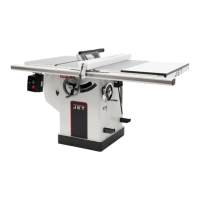
712 only: Install work stop rod into hole and
tighten knurled nut (H
2
). Slide stop block onto
rod and secure with thumb screw. See Figure
6-7.
Figure 6-7: installing work stop (712 only)
6. Slide pulley cover (A, Figure 6-8) over spindles
and secure with screws and washers
(HP2/HP3), using 10mm wrench.
7. Install lock screw (HP1) to secure pulley cover.
Figure 6-8: installing pulley cover
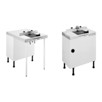
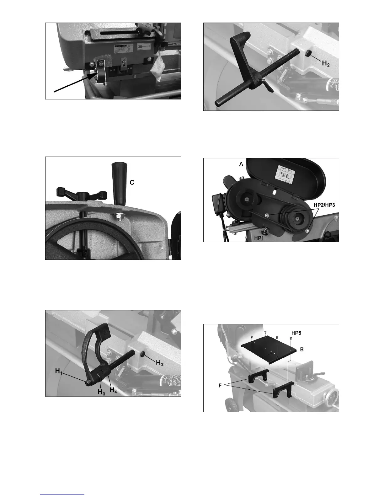
8. The table plate (B, Figure 6-9) may be used as
cutting table in vertical mode (models 712 and
712D), or may be used as infeed table in
horizontal mode (712D only). To use as infeed
table for model 712D, place supports (F) on
channel of saw bed as shown, and install plate
with flat head screws (HP5).
To use plate as cutting table in vertical mode,
refer to sect. 7.2.
Figure 6-9: installing infeed table (712D only)
9. Place filter assembly (G, Figure 6-10) over drain
hole.
 Loading...