17
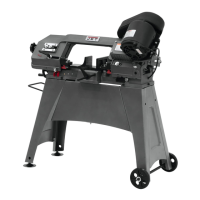
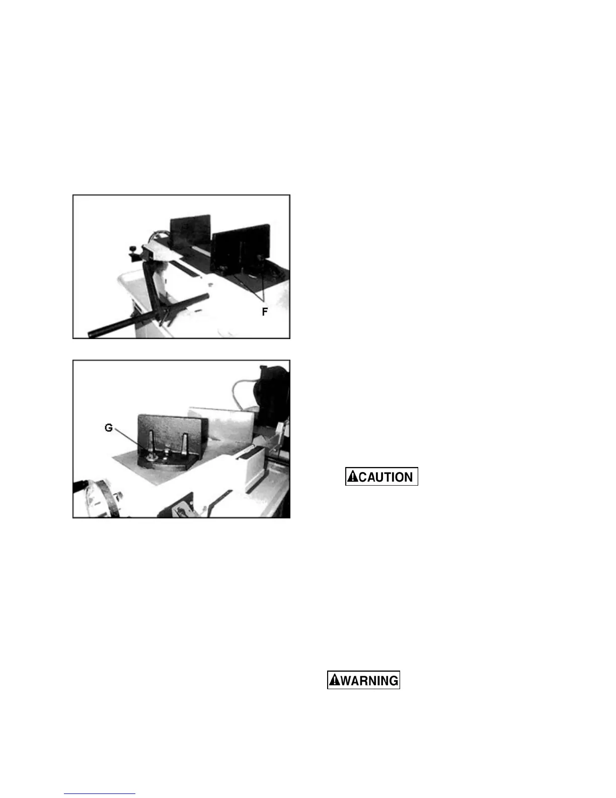
8.16 Vise positioning (712 only)
To set vise for 90 to 45 degree cutting:
1. Remove bolt and nut assemblies (F, Figure 8-
17).
2. Position vise and reinstall as shown in Figure 8-
17. Pay particular attention to bolt hole location.
3. Set vise to desired angle, reinstall nuts and
bolts, and tighten nut and bolt assemblies.
4. Adjust floating vise parallel to fixed vise by
loosening bolt (G, Figure 8-18), adjusting to
parallel, and tightening bolt.
Figure 8-17: vise positioning (712 only)
Figure 8-18: vise positioning (712 only)
To set vise for maximum width of stock cutting:
1. Remove nut and bolt assemblies.
2. Position vise and reinstall bolt assemblies as
shown in Figure 8-17.
9.0 Operation
9.1 Blade break-in
New blades are very sharp and, therefore, have a
tooth geometry which is easily damaged if a careful
break-in procedure is not followed. Consult the
blade manufacturer’s literature for break-in of
specific blades on specific materials. However, the
following procedure will be adequate for break-in of
JET-supplied blades on lower alloy ferrous
materials.
3. Clamp a round section workpiece in the vise.
The workpiece should be 2 inches or larger in
diameter.
4. Set the saw on low speed. Start the cut with a
very light feed rate.
5. When the saw has completed 1/3 of the cut,
increase feed rate slightly and allow saw to
complete the cut.
6. Keep the same hydraulic cylinder setting and
begin a second cut on the same or similar
workpiece.
7. When blade has completed about 1/3 of cut,
increase feed rate. Watch chip formation until
cutting is at its most efficient rate and allow saw
to complete the cut (see sect. 9.3, Evaluating
cutting efficiency).
8. The blade is now ready for regular service.
9.2 General operating procedure
IMPORTANT: When cutting magnesium, never use
soluble oils or emulsions (oil-water mix) as water will
greatly intensify any accidental magnesium chip fire.
See your industrial coolant supplier for specific
coolant recommendations when cutting
magnesium.
1. Give machine an overall inspection. Verify that
all guards, covers, etc. are in place and in
working order, the blade is tensioned properly
and tooth direction matches arrow on bow.
Check that blade guides and wire brush are set
correctly.
2. Raise bow until it will clear workpiece by a few
inches, and secure in position by closing
cylinder valve.
Always secure bow in
raised position before loading material.
Never start a cut with blade contacting
workpiece.
3. Position workpiece in vise and tighten vise.
Workpiece should be fitted directly between the
jaws without adding other objects. When work
piece is profiled section, flat piece or special
shape, refer to examples in Figure 9-1 for
proper clamping positions. The top row shows
acceptable clamping positions, the bottom row
show unacceptable positions.
If the thickness of profile section is very thin, a
piece which duplicates the profile should be
fitted inside the workpiece itself, to prevent
workpiece being crushed between the jaws.
Do not load/unload material
from vise while machine is running. Never hold
workpiece by hand when cutting; workpiece
must be firmly secured in vise. Do not reach into
cutting area during cutting operations.
 Loading...