7
8.0 Assembly
Never connect the machine to
the power source until assembly is completed.
Failure to comply may result in serious injury!
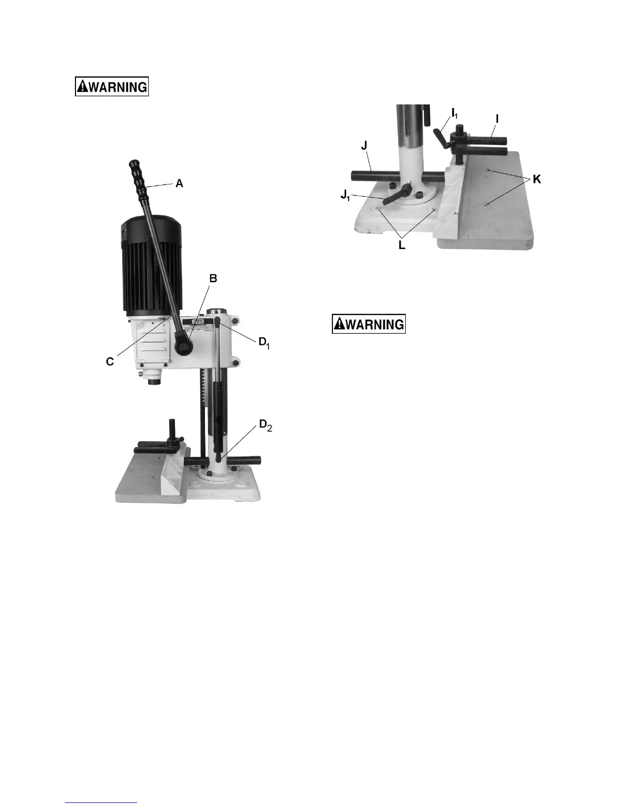
1. Screw handle (A, Figure 8-1) into clutch block
(B, Figure 8-1).
Figure 8-1
2. Tighten handle. The handle has a notch (C,
Figure 8-1) to accommodate a wrench.
3. Use handle to raise machine head to its
highest position. The handle is spring-loaded
and can be repositioned by pulling handle and
clutch block away from machine and
repositioning it on shaft (See Figure 10-2).
4. With head in the up position, press the
hydraulic cylinder onto the two fittings. The
upper fitting (D
1
, Figure 8-1) is located on the
head. The lower fitting (D
2
, Figure 8-1) is on
the column.
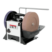
5. Attach table to base using two flat head
screws (K, Figure 8-2).
6. Insert bar of fence assembly (J, Figure 8-2)
through hole in column. Use the fence-locking
handle (J
1
) to adjust fence assembly.
7. Attach the hold down (I, Figure 3) to the
vertical post using wing screw (I
1
, Figure 3).
Figure 8-2
9.0 Installing
Make sure the Mortiser is
attached to a firm and stable support surface.
This machine must be fastened to a supporting
surface to prevent it from tipping during operation.
The base has four 3/8” diameter holes (L, Figure 8-
2) for this purpose. Mounting fasteners are not
included.