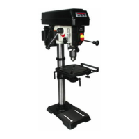
Figure 13
7.2 Extension cords
The use of extension cords is discouraged; try to
position equipment near the power source. If an
extension cord becomes necessary, be sure to use
one heavy enough to carry the current your product
will draw. An undersized cord will cause a drop in
line voltage resulting in loss of power and
overheating. Table 1 shows correct size to use
depending on cord length and nameplate ampere
rating. If in doubt, use the next heavier gauge. The
smaller the gauge number, the heavier the cord.
Ampere
Rating
Volts Total length of cord in feet
More
Than
Not
More
Than
120 25 50 100 150
AWG
00 06 18 16 16 14
06 10 18 16 14 12
10 12 16 16 14 12
12 16 14 12
Not
Recommended
Table 1: Extension Cord Recommendations
8.0 Adjustments
8.1 Tools needed for adjustments
Pliers
13mm wrench
24mm wrench (provided)
Rubber mallet
8.2 Table movement
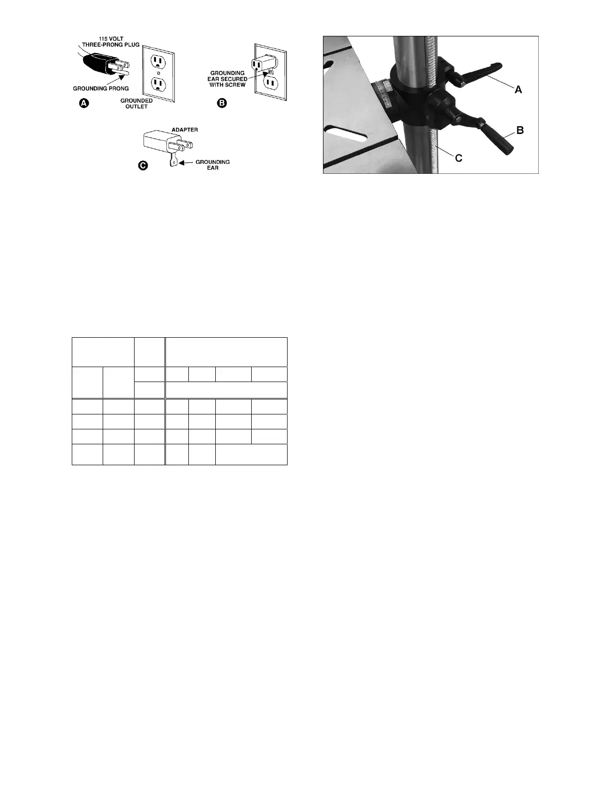
8.2.1 Table raising and lowering
Refer to Figure 14.
Loosen column locking handle (A, Figure 14). Turn
table elevating handle (B) to raise or lower table
along column rack. Re-tighten locking handle (A)
before attempting to drill.
Figure 14
8.2.2 Table repositioning
Refer to Figure 14.
When drilling into a long workpiece, swing table out
of the way and use drill press base as your table.
Slots in the base can be used to mount work holding
devices.
1.
Loosen column locking handle (A).
2.
Swing table around the column. If rack (C)
tends to bind, you will need to
nudge the top or
bottom
end of the rack around the column while
swinging table.
3.
Tighten column locking hand
le (A).
8.2.3 Table tilting
Refer to Figure 15.
1.
Turn nut (D) clockwise with 13mm wrench to
extract the alignment pin (E). The alignment pin
is tapered and will back out as the nut is turned.
2.
Remove alignment pin.
3.
Loosen hex cap screw (F), with provided 24
mm
wrenc
h, and tilt table to desired angle us
ing the
angle s
cale.
4.
Tighten the hex cap scr
ew (F).
The alignm
ent pin (E) only works at 90° and must
be reinserted when the table is returned to 90°.
Reinsert the alignment pin, along with the nut, and
tap it lightly with a rubber mallet for full insertion.
 Loading...