4. Tighten lock handle (G).
5. The bit will now stop at the mark
ed depth when
the downf
eed handle is
rotated.
6.
To release the depth stop, loosen lock handle
(G).
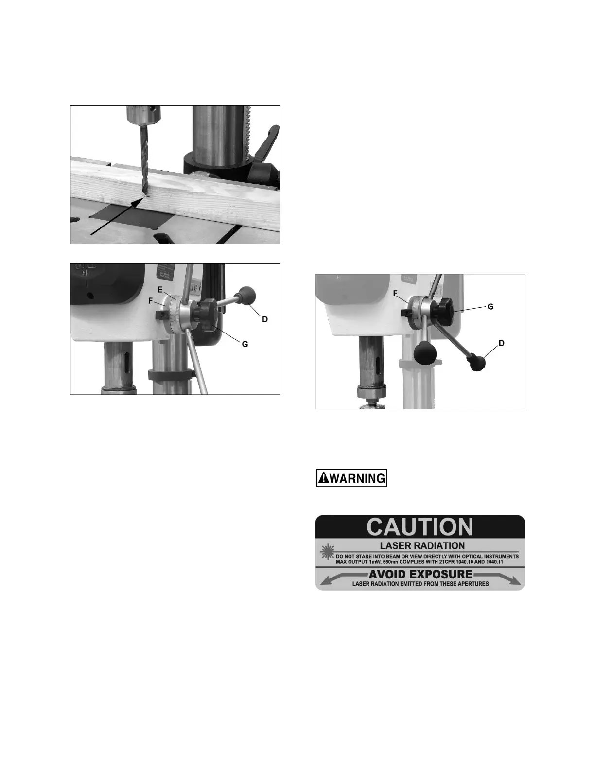
Figure 22
Figure 23
NO
TE: Method #2 allows rapid, fine adjustment to
the setting, as follows:
If the depth setting is found to be too shallow:
1.
Hold downfeed handle (D) stationary while
slightly loosening lock handle (G).
2.
Slightly rotate downfeed handle to lower bit to
the more accurate pos
ition.
3.
Retighten lock handle (G). Depth is now set to
more accurate pos
ition.
If
the depth setting is found to be too deep:
1.
Loosen lock handle (G) while holding downfeed
handle stationary.
2.
Slightly back off the lock ring (F), that is, rota
te
it
clockwise
.
3.
Slightly rotate downf
eed handle to bring bit up
to m
ore accurate depth.
4.
Rotate lock ring (F) all the way counter-
clockwise.
5.
Tighten lock handle (G). Depth is now set to
more accurate pos
ition.
8.9 Quill retraction lock
The quill can be held in the down position and
prevented from retracting, such as for operating a
sanding drum or to facilitate removal of chuck and
arbor.
To lock the quill in down position, proceed as follows
(Figure 24):
1.
Loosen lock handle (G, Figur
e 24).
2.
Rotate downfeed handle (D) to lower spindle to
the point at which it is to be locked, and hold
downfeed handle stationary in this position.
3.
Rotate lock ring (F) clockwise all the way until it
stops. You should be able to feel and hear when
the lock ring reaches the end of its rotation.
4.
Tighten lock handle (G). You can now releas
e
downf
eed handle. The quill will remain in this
lowered position until released
.
5.
To release the quill, loosen lock handle (G).
Figure 24
8.10 Laser adjustment
Refer to Figures 25, 26 and 27.
Do not look directly into the
laser beam or view it directly with optical
instruments. See Figure 25.
Figure 25
The Laser Assembly has been installed and pre-set
at the factory. It should, however, be checked for
alignment and any adjustments made before
operating the drill press. It should be re-checked
periodically, as long-term machine vibration may
cause it to become misaligned.
1.
Position table at the horizontal (zero degrees
on
sca
le).
2.
Insert a small drill bit into the chuck.
 Loading...